 .ORG - We're getting ready to move!
A few different methods:
| 1 | Test Setup | Connect a NinoTNC to the specific transmitter it will be used with, and set up power sources for the TNC and radio.
Place a dummy load onto the transmitter’s RF connection, and set the transmitter to its lowest power setting. This particular deviation meter uses a scanner (here a Radio Shack Pro2010, but most any scanner can be made to work). I recommend a Uniden BC335, which works well with this deviation meter kit from Masters Communications. Normally it is not necessary to connect the transmitter's antenna to anything more than a dummy load, and on low power. The scanner will pick up the signal without any physical connection. |
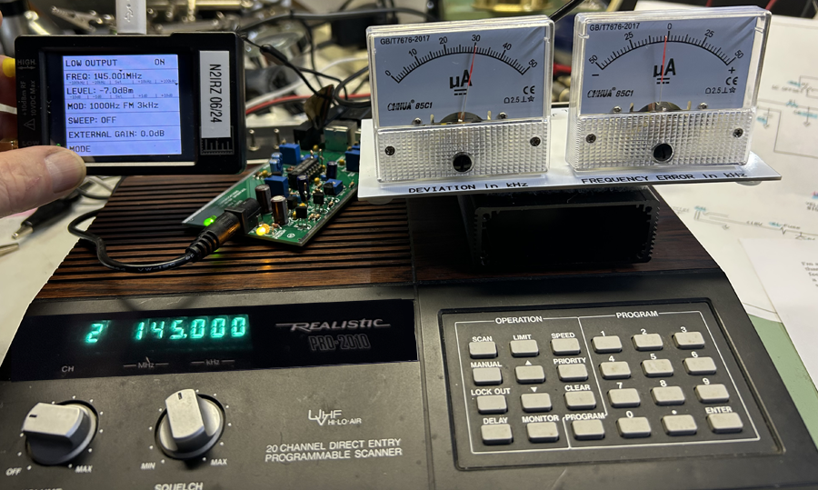 Sample test setup, with a "transmitter" (here a TinySA in signal-generator mode) at the left, and my deviation meter & scanner on the right. The 'bare board' to the left of the scanner is the deviation meter, out of its case (the black rectangle beneath the analog meters). |
| 2 | Adjust | With the deviation meter set up and on frequency (there are so many kinds, you'll need to know how to do this), press the Test
TX button on the TNC. Adjust the TX Dev pot until the meter reads 2.4 kHz. That's all! |
| 1 | Test Setup | Connect a NinoTNC to the specific transmitter it will be used with (suitable for 9600 baud operation), and set up power sources for the TNC and radio. Place a dummy load onto the transmitter’s RF connection, and set the transmitter to its lowest power setting. |
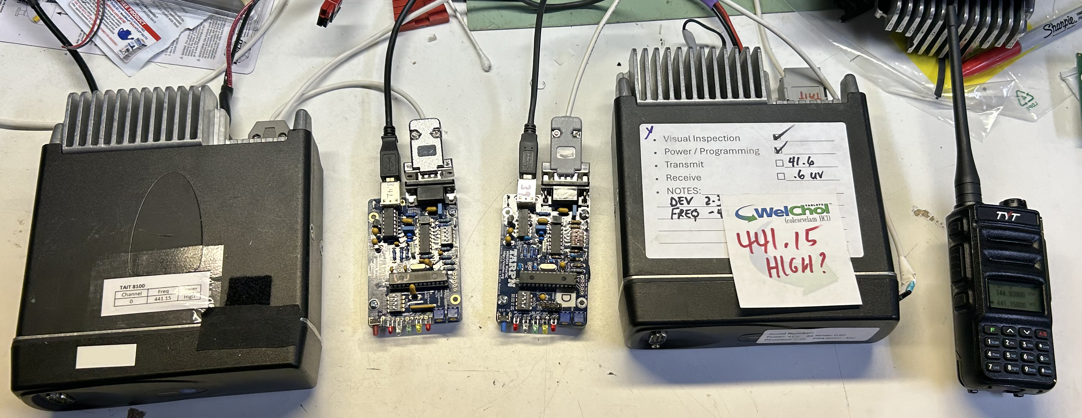 The complete test setup, transmitter on the left, receiver on the right. The HT is only used to monitor audio. |
| 2 | Receiver | Connect a second NinoTNC to a receiver suitable for the mode. (By that, I mean a radio that is normally capable of receiving 9600 baud transmissions properly - an HT won’t do). Again, set up power for the TNC and radio |
| 3 | Scope Setup | Set your Oscilloscope to 40 microseconds (uS) and 500 mV per division, then connect the probe to the receive TNC’s ground and RXA test points. Triggering should be for the same channel as the probe, and at or just a bit over 0 volts. The channel should be AC coupled |
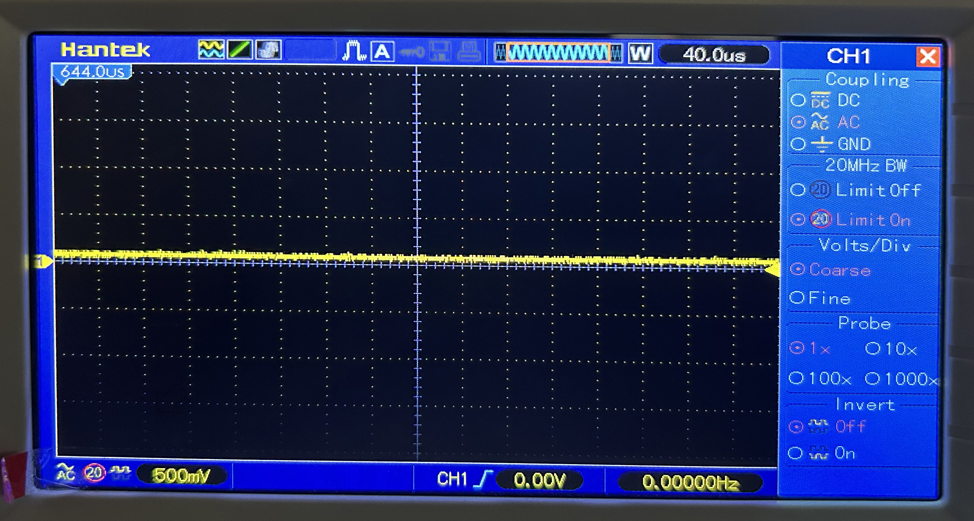
This image shows the oscilloscope screen and setting |
| 4 | Check that the scope is connected | When you press the TX Test button, a sine wave should be visible on the scope display, although its amplitude depends on the TX Dev potentiometer setting. It may be very large. |
| 5 | Enter Test Mode | Press and hold the transmit TNC’s test button for about 12 seconds: For the first 10 seconds nothing unusual will happen, but then the LEDs on the TNC will light from left to right. LET GO of the test button when the Green LED lights, which starts the Eye Pattern transmission. NOTE: If you are too slow, the yellow LED will light and the TNC will send out a test packet every second for 120 seconds. To exit either of these modes, press and hold the test button again until you see the sine wave again, then release it. Cycling power will NOT reset these modes! The image to the right shows four LEDs lit. Pressing the test button always lights the right-most Red LED immediately; Holding it for 10 seconds has the other LEDs lighting in order from left to right. Here we see the Green LED lit, but not the Yellow LED. Let go of the test button as soon as the Green LED lights to enter the eye pattern test mode. See the The NinoTNC Operator's Manual (Chapter 20) at TARPN.net for more information on Test modes. |

|
| 6 | Adjust | Adjust the TX Dev potentiometer on the transmit TNC until you see the best “eye pattern”. “Best” in this case means a good, hollow ‘eye’ with not much ripple at the top and bottom ‘rails’. The crossover points should tend to be clean and stable, but it is to be expected that the trace will jump around a bit. Note that your transmitter may time out, in this case start over again. | These two are "good" eye patterns. They are difficult to capture well with a camera.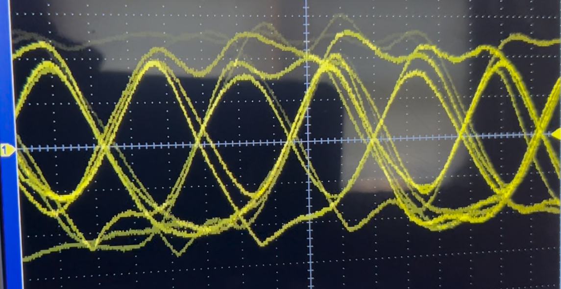 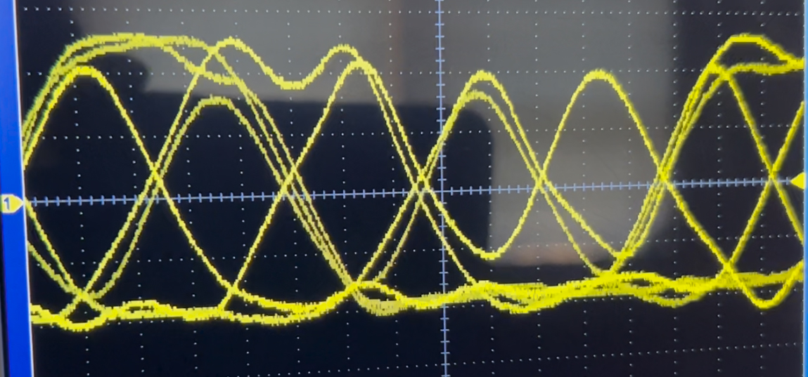 This signal is too low 
This signal is way too high 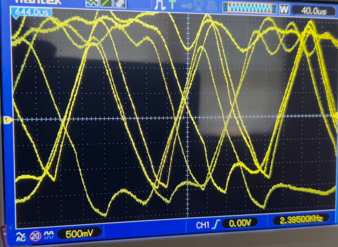
This signal is just a little too high 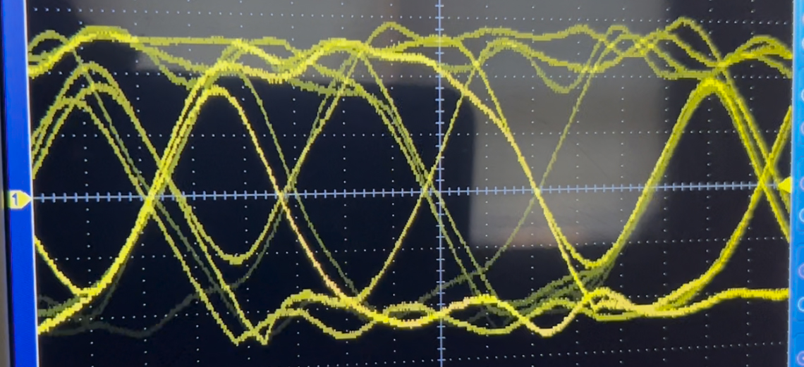
|
Please send in any comments, corrections or suggestions. Thanks!
This website is maintained by Don Rotolo, N2IRZ. Contact me via the information on QRZ.COM