 .ORG - We're getting ready to move!
While this TARPN NodeBox is a compact, feature-rich solution for node contruction, there are an infinite number of other ways to put (and hold) a node together. This document shows how to assemble a NodeBox that has been shipped to you. Generally these are handed out in person, fully assembled, but without anything inside. These cost about $25 to fabricate - plywood is expensive these days.
NOTE: Some images are still pending.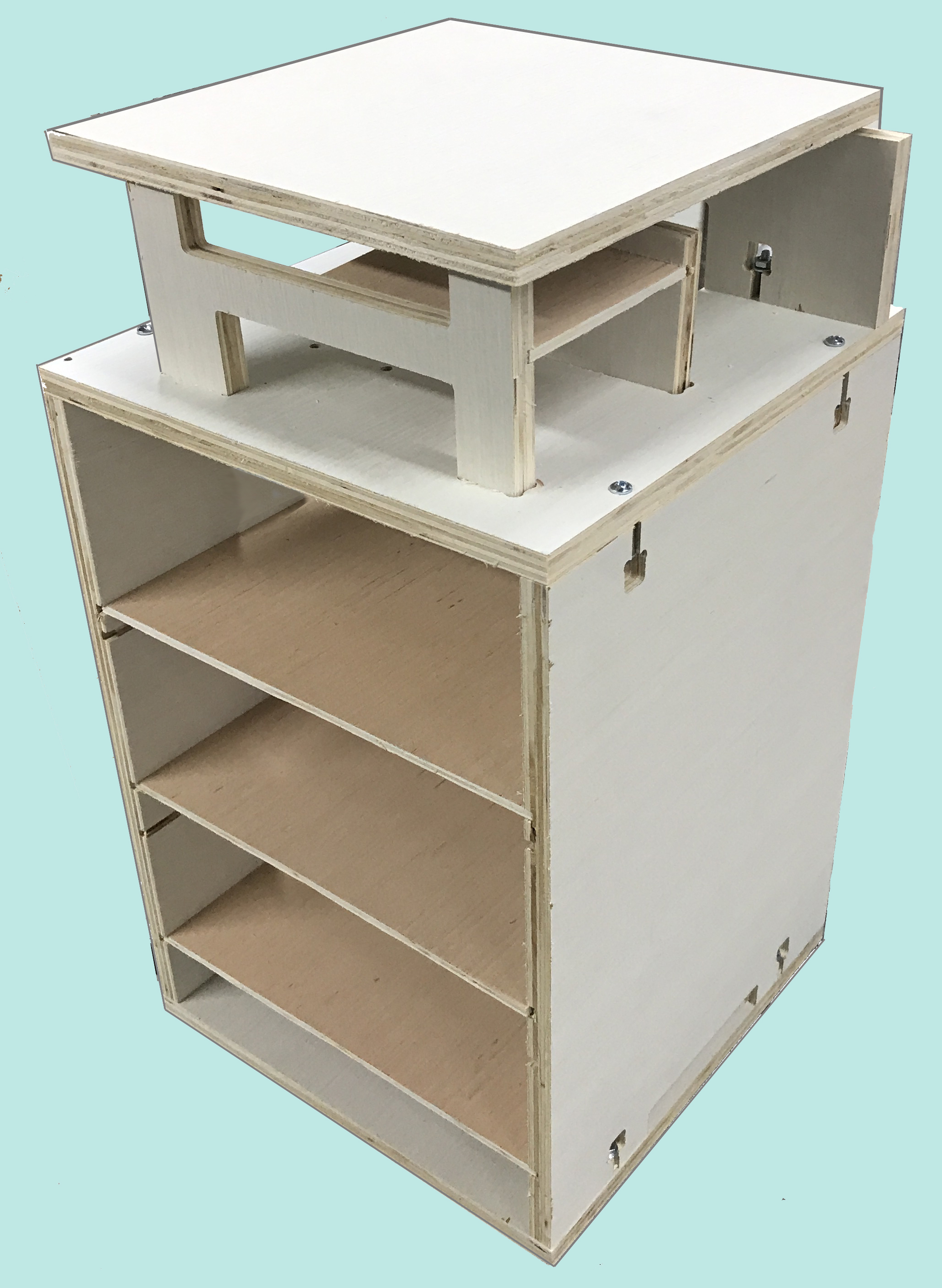
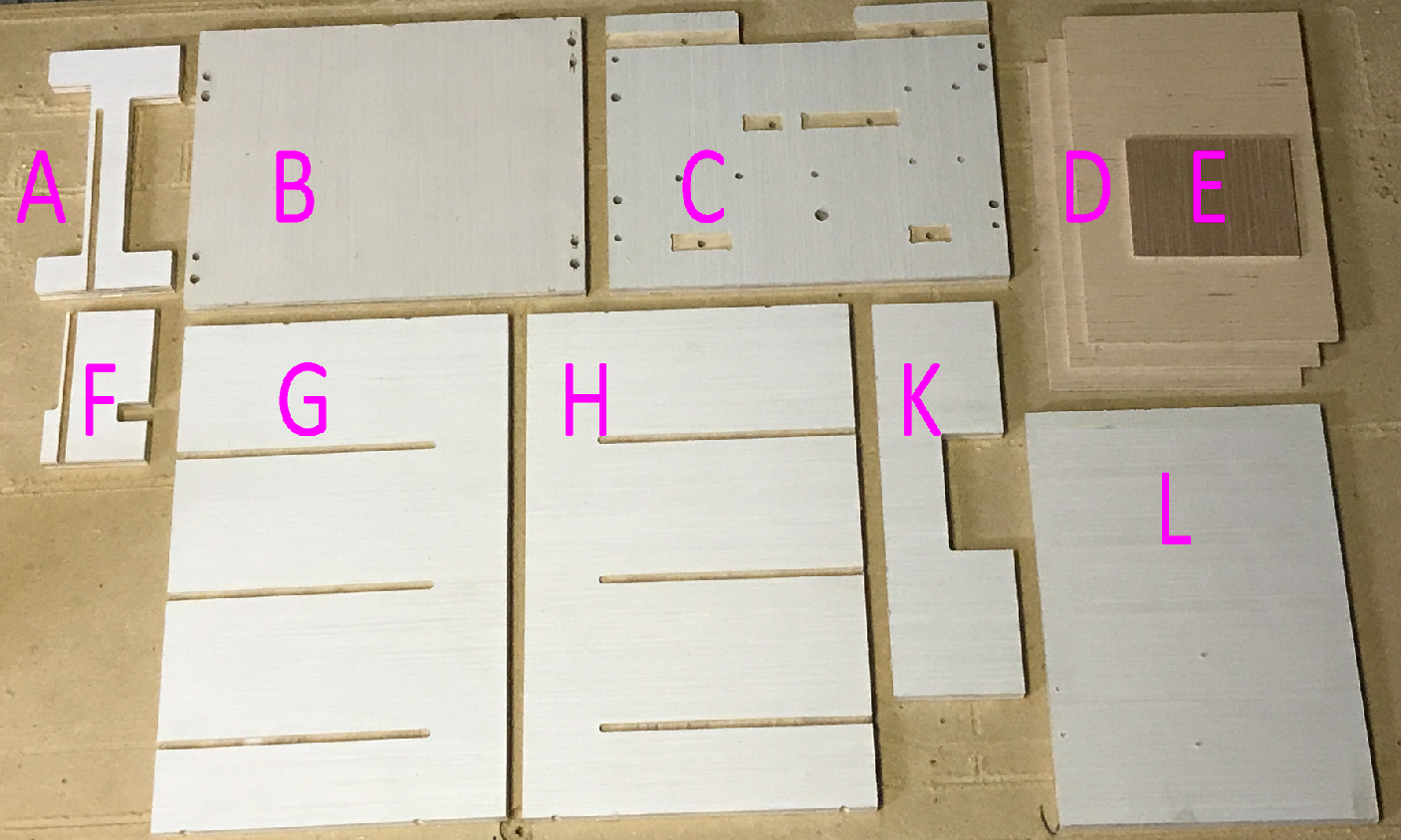
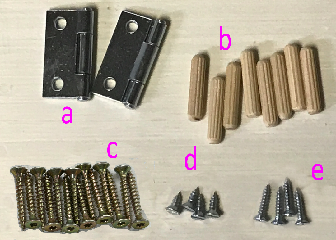
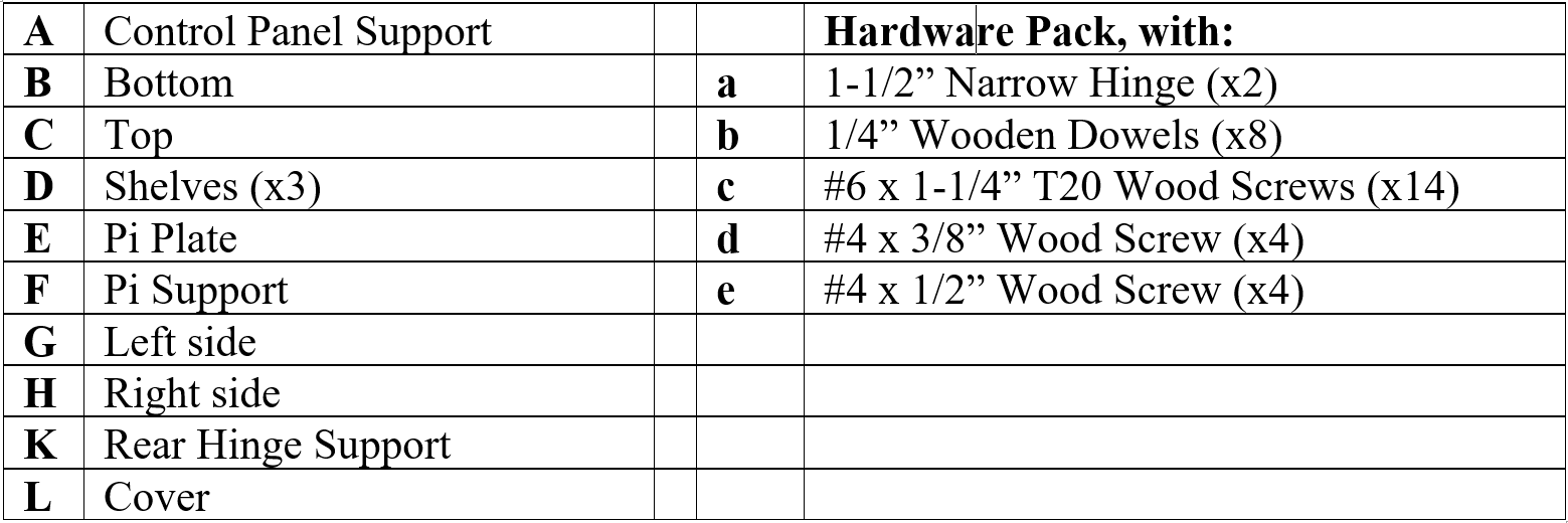
Items in the kit: |
|
|
Notes:
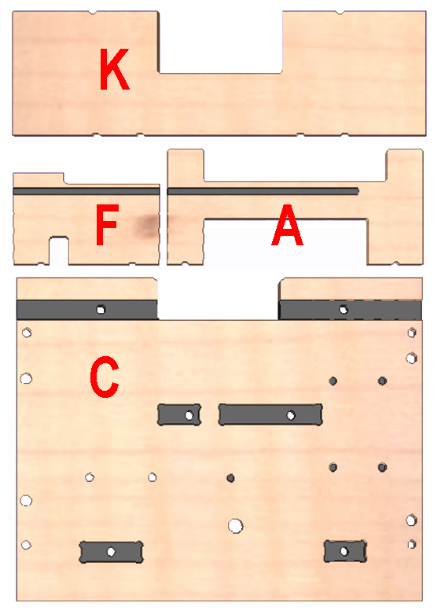
| 1 | Assemble the Top | Collect the parts shown:
|
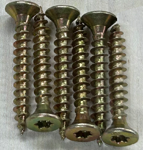 |
| 1.1 | Insert the Pi Support (F) completely into the Top (C) pocket as shown and fasten it from underneath with two #6 1-1/4” Wood Screws (c) through the pre-drilled holes. Make sure the Pi Support is upright. |
| 1.2 | Insert the Control Panel Support (A) completely into the Top (C) pocket as shown and fasten it from underneath with two #6 x 1-1/4” Wood Screws (c) through the pre-drilled holes. Make sure the Control Panel Support is upright. |
| 1.3 | Insert the Rear Hinge Support (K) completely into the Top (C) pocket as shown and fasten it from underneath using two #6 x 1-1/4” Wood Screws (c) through the pre-drilled holes. Make sure the Rear Hinge Support is centered on the Top side-to-side and is upright (i.e., perpendicular to the Top’s surface, not leaning). |
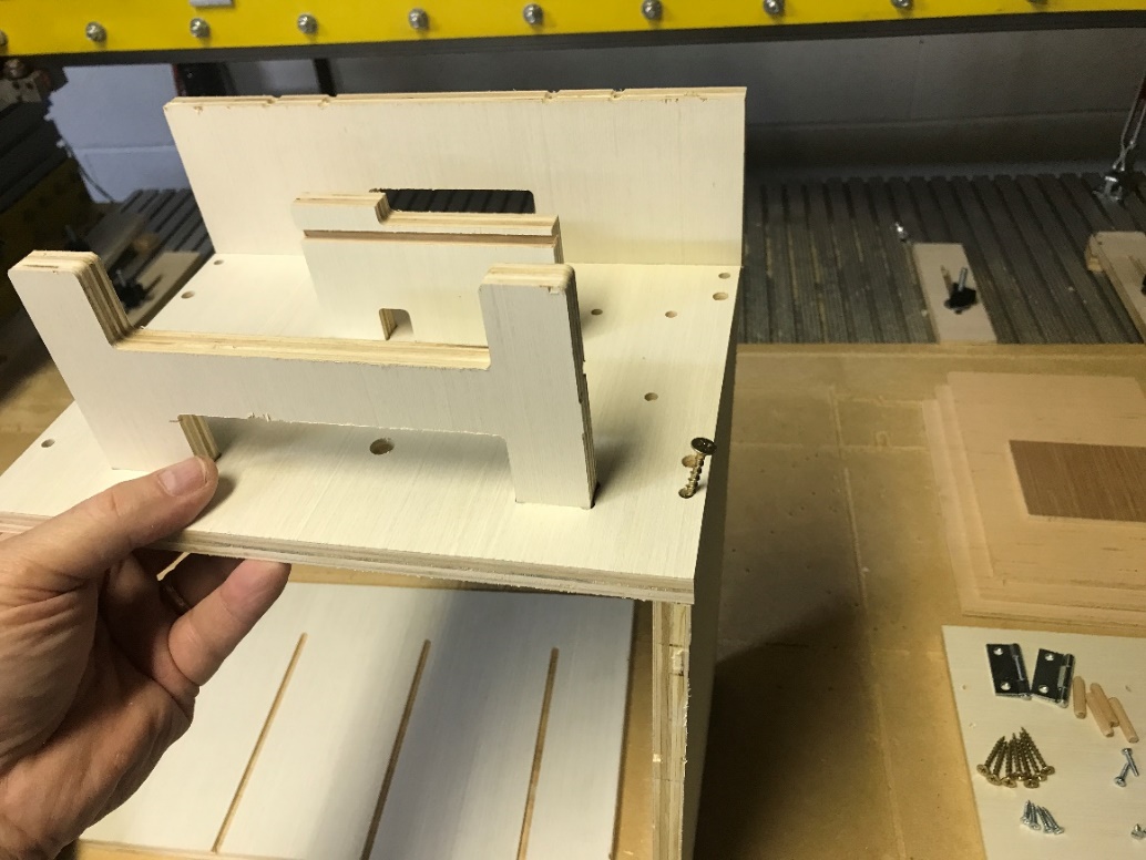
This image shows the top with all three Supports installed |
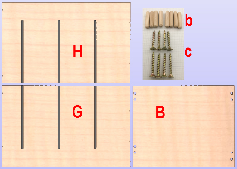
| 2 | Assemble the Box | Along with the completed top (C) assembly from the previous step, collect the parts shown:
|
|
| 2.1 | Insert two Wooden Dowels (b) into the two holes drilled in each end of both the Left Side (G) and the Right Side (H), a total of eight dowels (four ends with two dowels each) | 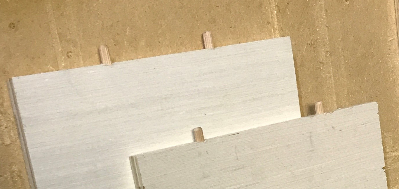
|
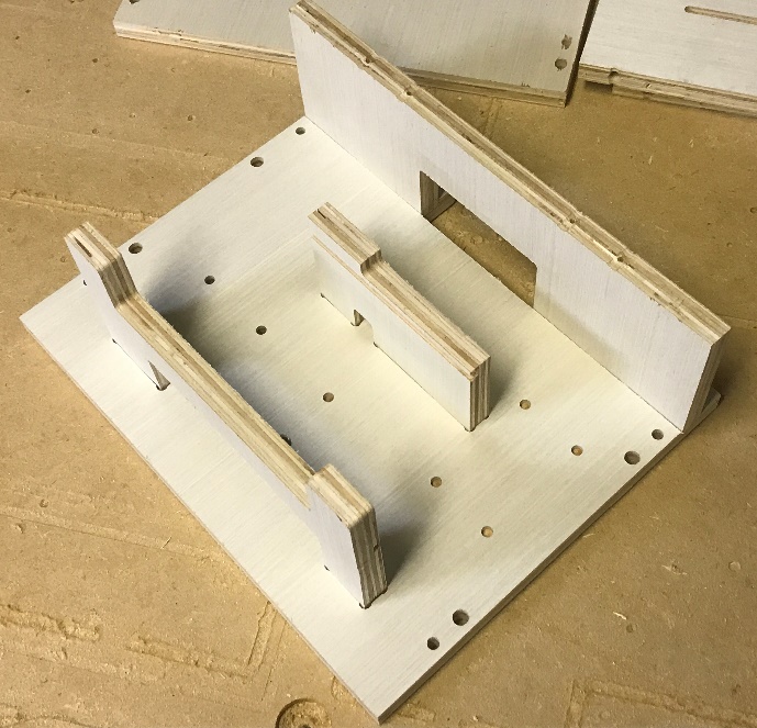
| 2.2 | Place the pre-assembled Top (C) on to the Left Side (G) over the Dowels as shown.
Note that the Sides will fit only one way, with the Side’s grooves towards the middle of the box, the uncut end of the groove towards the rear, and the smallest groove ‘space’ towards the bottom. The hole spacing varies for each end of the sides. |
This image shows the front right screw at an angle - this is bad. See the next step. |
| 2.3 | Fasten the Top to the Left Side using two #6 x 1-1/4” Wood Screws (c) through the pre-drilled holes in both the top and the sides. Be sure the screws are driven directly downwards (vertical), not slanting one way or the other, otherwise the screw can come out of the wood side. |
| 2.4 | Repeat for the Right Side (H). Your box should look like this. | 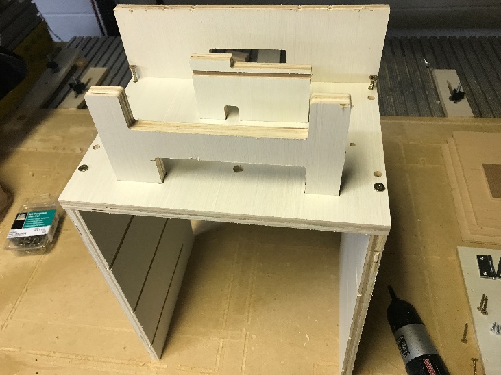
|
| 2.5 | Fasten the Bottom (B) to the Left (G) and Right Sides using four #6 x 1-1/4” Wood Screws (c) through the pre-drilled holes. Again, the bottom will fit in only one orientation. | 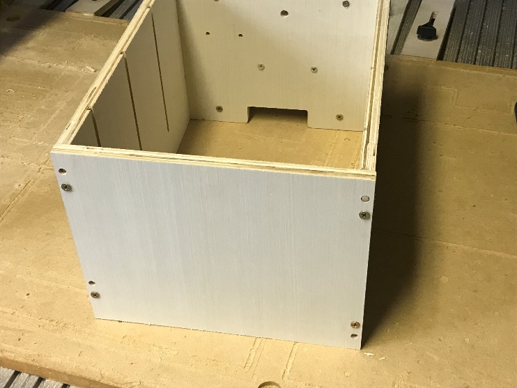
|
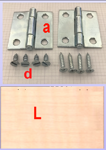
| 3 | Attach the Cover | Along with the assembled box from the previous step, collect the parts shown:
|
|
| 3.1 | Temporarily position the two 1-1/2” Hinges (a) on top of the Cover (L) as shown, with the hinge’s pins facing up. Note the pre-marked screw holes on the Cover. | 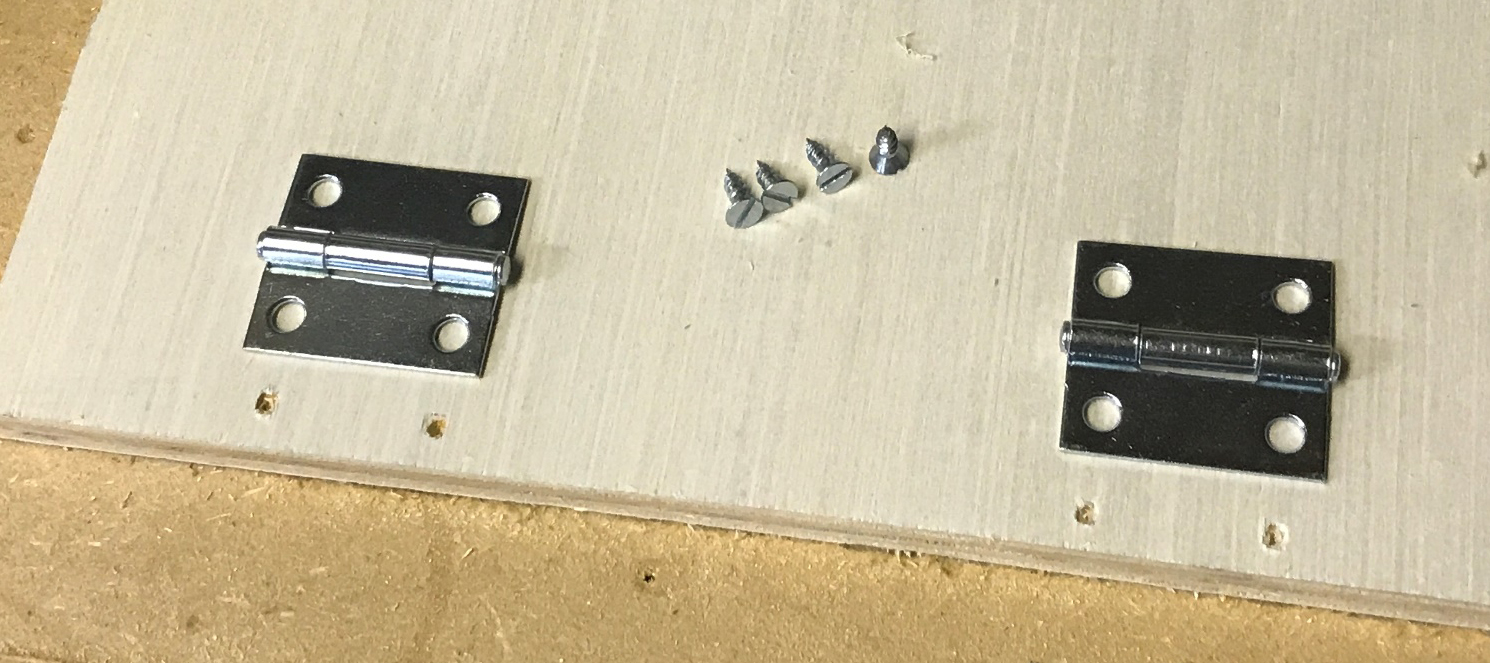
|
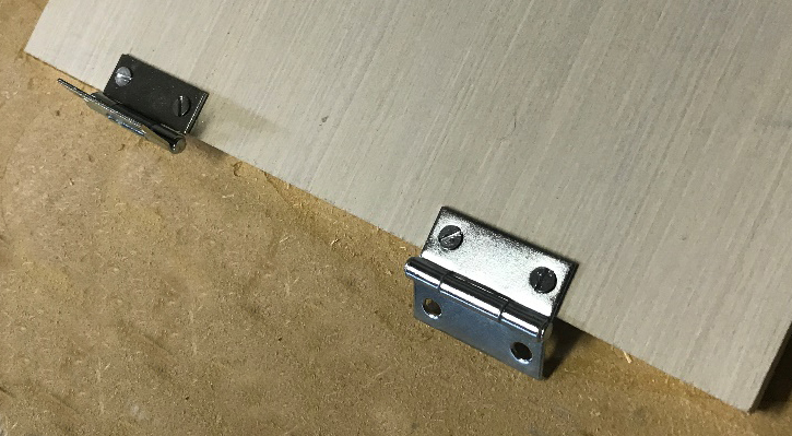
| 3.2 | Using the #4 x 3/8” Wood Screws (d), re-position and attach each hinge to the top as shown, overhanging the edge, with the pins on top. Do not overtighten the screws, but make them reasonably flush with the hinge surface. They will be slightly proud (stick up a bit) of the hinge surface. Warning: Be sure the 3/8” screws are used, or they will penetrate the cover! |
|
| 3.3 | Place the Cover onto the Rear Hinge Support (K) with the hinges positioned as shown, aligned with the pre-drilled holes in the top edge of the Rear Hinge Support. Using four #4 x 1/2” Wood Screws (e) fasten both hinges to the top edge of the Rear Hinge Support. | 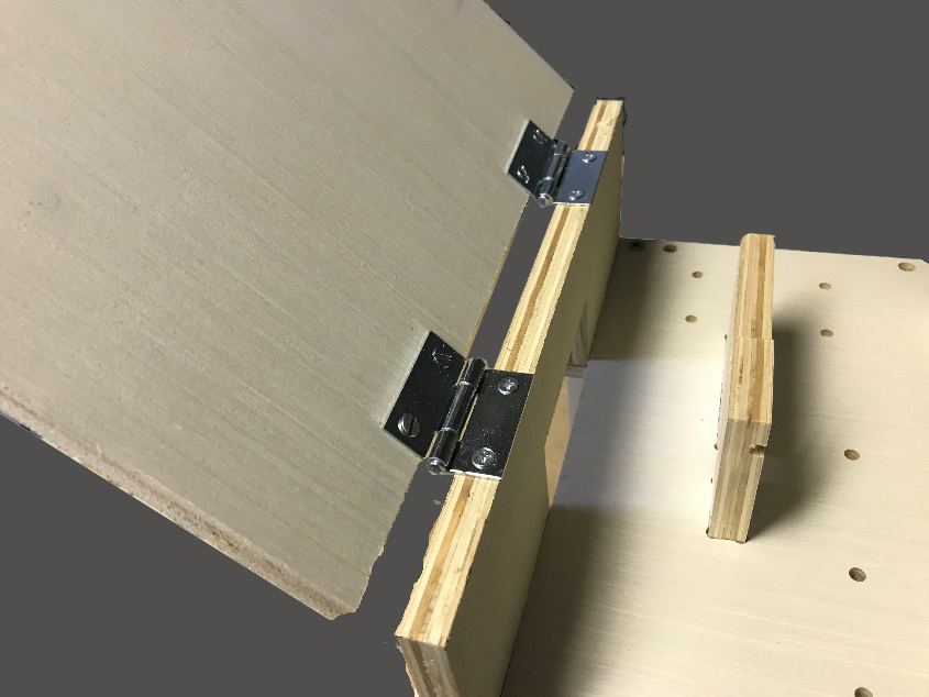
|
| 4 | Installation Tips | This completes the NodeBox Assembly. Now some tips on installing your Node hardware.
|
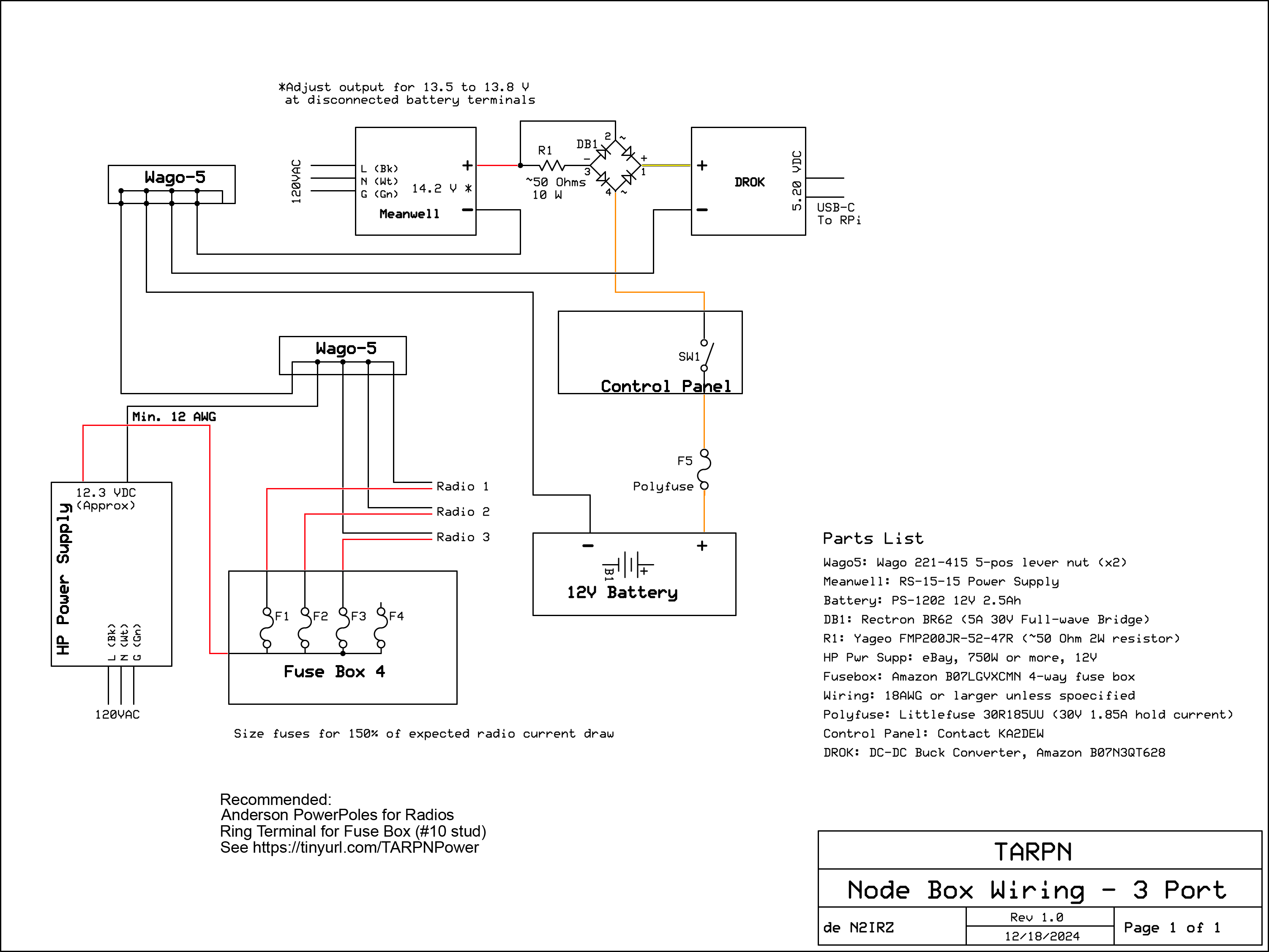
Click the image to download the PDF version |
This website is maintained by Don Rotolo, N2IRZ. Contact me via the information on QRZ.COM
Updated 3MAR2025