Wiring Instructions for the N2IRZ TARPN NodeBox
Now that you've built (or received) an N2IRZ TARPN NodeBox, it needs to be filled with parts and wires. There are as many ways to do this as there are node boxes. What is presented here is one way that has been found to work time and time again. Having a 'standardized' node system also helps with troubleshooting.
Note that the level of detail presented here is probably overkill. Nevertheless, if you prefer a high level of detailed information, particularly to give you confidence in your actions, we've got you covered. Feel free to improvise, at your own risk of course.
This document shows how to set up and wire a NodeBox that has been assembled. You can expect to spend up to $200 if you buy everything new, but many of us have collectively invested in equipment, generally obtained at a discount, which we can loan or sell to you. For loans, eventually you'll pay it back or pay it forward.
NOTE: Prices shown are typical, not including shipping.
We have tried to include specific details for every step, but once we've covered a particular technique (such as how to use a screw-clamp terminal), we won't bring it up again as we presume you'll remember from previously. If you've forgotten or are not sure, work backwards to find the specific technique you want to use. Or, of course, just ask us.
NOTHING HERE IS ABSOLUTELY CRITICAL: Feel free to substitute, but ONLY if you know what you're doing. These items have been carefully researched for good performance at the lowest possible price. If there is a thing you can get at a significantly lower price, there is likely a reason we did not choose that version: Please ask us before you head off in a different direction, we're happy to explain our reasoning. Of course, one never knows if you've found a better thing for less: if so, we'd like to hear about it, too.
In this document, it is assumed that you have some basic tools and equipment, such as:
- Wire cutters
- Wire strippers
- Screwdrivers (Phillips and Flat, regular and small)
- Soldering iron & electronics solder
- Crimper for crimp-on terminals, or big pliers
- A basic ruler, in inches
- Needle-nose pliers
- Ideally, a crimper for Anderson PowerPole 15/45 connectors
These tools should be sufficient to complete the node box wiring. If you don't have something, and can't borrow it from a friend or neighbor, there's nothing terribly critical about any of them: With a little creativity, other things can be used instead. While we strongly advise using the right tool for the job, sometimes that swiss army knife (or butter knife) can come in handy. Just be careful to not injure yourself. Finally, note that places like Harbor Freight might sell you all of these things for less than the price of dinner at Applebees.
This process consists of five major steps:
- Collect the Items You Will Need
- Prepare the Components
- Install the Components
- Wire the Components
- Adjust and Test the System
- We then offer some operating tips
A. Collect the various items you will need:
| A.1 |
Node Box
|
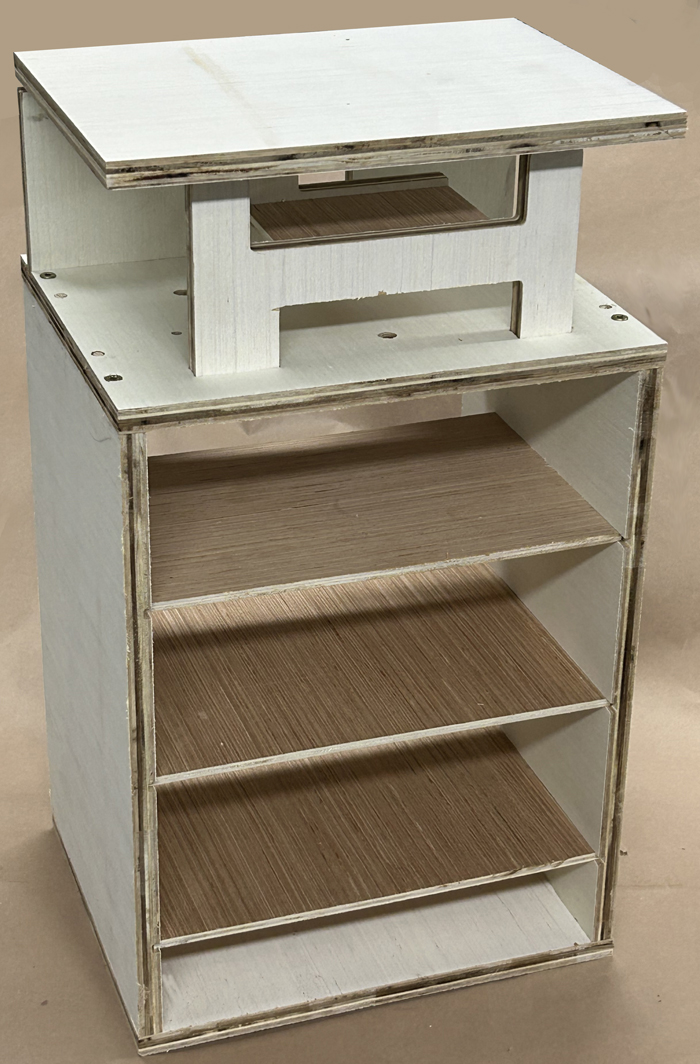
A fully-assembled N2IRZ TARPN 3-Port NodeBox, which holds everything together in a compact, convenient and robust system. Contact N2IRZ for availability.
|
|
| A.2 |
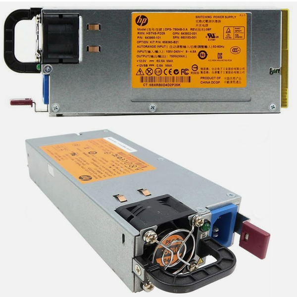
HP Power Supply
|
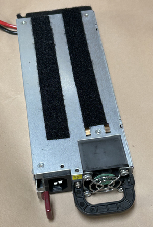
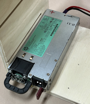
A surplus Hewlett-Packard Server power supply has proven to be a highly-reliable yet inexpensive source of clean and quiet 12 volt power for the node radios. Look for the 750 Watt version, with the orange label, but other versions (such as the green-label 1200 Watt version) are fine, as long as they can deliver the needed amperage. We have found these on eBay for under $20 reliably. Search "750 HP power supply".
|
|
| A.3 |
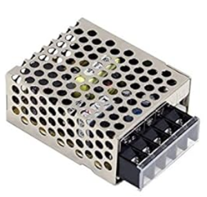
Battery Charger Supply
|
The Battery Charger power supply is used to charge the Pi Backup Battery, and indirectly power the Raspberry Pi.
- One version, using the Meanwell RS-15-15 supply (typically $11) plugs into the wall (110 VAC) and delivers the necessary voltage. This can be purchased from many outlets, including Digikey, Mouser, eBay and Amazon. The downside of this excellent power supply is its need for a second AC power cord. We recommend you instead consider:
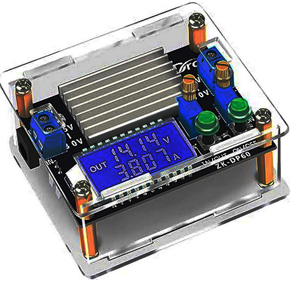
- The DROK 200446 buck/boost converter (typically $17) and is powered from the HP Power supply, eliminating the need for two house-current wall plugs. We've only seen this on Amazon.
It is your choice whether the inconvenience of needing two things plugged into the wall outweighs the $5 extra cost.
- For BOTH versions, you will want two M3 x 13mm screws to fasten it to the box. Longer screws will damage the Meanwell.
|
 |
| A.4 |
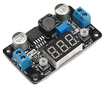
Pi Power Supply
|
The DROK 180057 Buck Converter ($10) power supply delivers clean 5.2 volt DC power to the Raspberry Pi, and is powered by either the Meanwell RS-15-15 or the HP Power Supply. We've only seen this on Amazon. There are less expensive options, perhaps without some features, so the key point is that it can accept at least 8 to 16 volts as input and can deliver exactly 5.2 volts (ideally adjustable, since 5.0 volts is not OK) and at least 2 Amps (11 Watts)
|
|
| A.5 |
Backup Battery
|
The PowerSonic PS-1220 lead-acid battery ($10) is used to deliver power to the Raspberry Pi when mains power fails, allowing for an orderly shutdown of the Pi. It was selected for its size and terminal type. The Raspberry Pi, like many computers, gets angry when power is removed from it unexpectedly. This can result in a fatal corruption of the MicroSD card that serves as the Pi's 'hard disk'. Avoid removing power unexpectedly! Instead, shut down the Pi either by using the Control Panel button, or via the Pi desktop menu.
We have found the best price for these at Battery in the cloud.
You are welcome to use a different battery (the 'charger' we use ONLY supports lead-acid chemistry! Definintely NOT any Lithium-based chemistry!). Mounting it becomes your challenge.
|

|
| A.6 |
Fuse Box
|
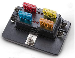
The Bunker Indust 4-way Blade Fuse Box ($10) is used to protect the node box wiring from excessive current draw. It has been selected because of its size and specific features: It uses ATO blade fuses, is rated to 30 Amps per circuit, has a single input terminal (#10 stud) and separate 1/4-inch quick connect output terminals. We've only seen this on Amazon.
|
 |
| A.7 |
Power Switch Circuit
|
The Power Switch Circuit delivers power to the Pi Power Supply from either the Backup Battery or Either of the RS-15-15 OR HP power supplies, whichever has the highest voltage. It does this instantly, with absolutely no delay. It consists of two components which must be assembled (which will be explained later):
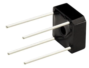
- A full-wave diode bridge, such as the Rectron BR62 ($0.78) available from Mouser. If you select an alternative (there are many) be certain it can handle at least 3 Amps and withstand a 50 V reverse voltage as minimums - higher values are more robust.
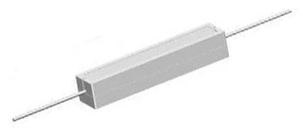
- A power resistor in the 50 Ohm range (47-52 is fine) rated for around 10 Watts. This is used to limit the charging current to the backup battery. These can be had from many places, for example the Yageo SQP10AJB-51R ($0.65), also from Mouser
|
 |
| A.8 |
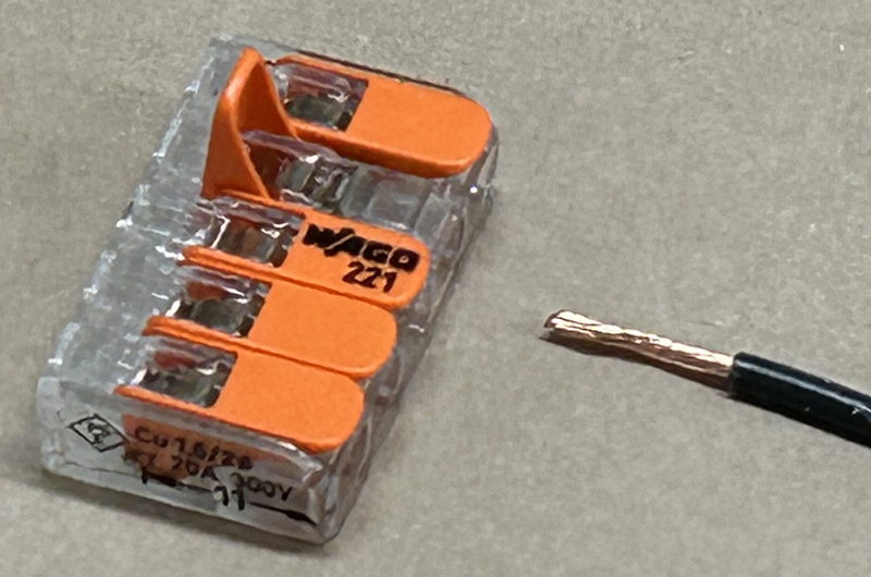
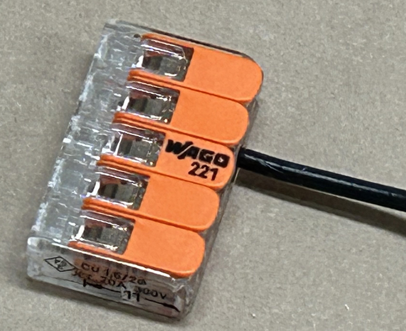
Wago Lever Nuts
|
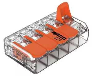
The Wago 221-415 5-way Lever Nuts ($1 each) are used to connect all of the various ground wires together. These are relatively inexpensive, simple to use, and marked with a 30 Ampere rating.
You will need TWO of these. Big-Box stores and Electrical supply houses sell these for around $9 for a pack of 10, but they can be had in larger quantities for as little as $0.50 each. If you have an electrician friend, they will probably hand you the two you need.There are many other possible solutions, including a "Ground Bus Bar" of the style used in AC Power electrical panels, but these have been found to be somewhat more costly.
|
|
| A.9 |
Control Panel
(Optional but strongly recommended)
|
A fully-assembled TARPN Control Panel, with ribbon cable. Please visit the
Control Panel section of the TARPN Builder's page for information.
Note that the latest version of the Control Panel uses four LEDs; while these version boards are available in the SPROING area, the instructions on the TARPN page are not yet updated to reflect the various changes from the three-LED version pictured here.
|

|
| A.10 |
Wire
|
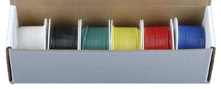
You will need several kinds of wire. The only important specifications are the wire gauge (size) and that the wire is made of copper. Copper-clad Aluminum (CCA) is very popular because it is far less expensive than copper, but it is crap: Avoid it like Covid. Colors are ideally the ones described here, particularly the paired red/black zip cord, but can be substituted as needed. Just don't use all the same color wire! That's a sure recipe for disaster.
Recommended are the following:
- An assortment of #18 wire in different colors. Search on Amazon for B085QD9DWP ($18). Others sell similar kits, just be sure it's #18 wire and stranded copper. No need for silicone insulation, PVC is fine.
- A few feet of #18 (or #16) red/black paired wires (zip cord, $8 for 25 feet of #18). Amazon sells a LOT of this, 99% of which is copper-clad aluminum that you definitely do NOT want. Instead try Powerwerx. They sell high quality product at very good prices.
- About a foot of #12 red/black zip cord ($25 for 25 feet). Also available from Powerwerx (see link above). Unfortunately the smallest length they sell is 25 feet. It comes in handy often, so if you can, get the whole 25 feet.
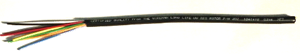
For all of these wire items, you can also visit The Wireman who sells it by the foot (and who is often at larger hamfests). The different color wire assortment can be had by buying a length (maybe 8 feet or so, at $1.45/ft) of their #302 Premium Rotor Cable, which comes with six #18 wires and two #16 wires wrapped in a single outer covering. Just remove the covering and you have eight suitable pieces of wire. Note that they often sell short end-of-reel offcuts at a discount in their clearance section - search their site for "302".
|

 |
| A.11 |
Other Bits & Bobs
|
Several other parts will be needed, widely available from many sources:
- One IEC Cord for the HP Power Supply and (if you use it) one for the Meanwell RS-15-15 Power Supply.
- A short (6", or longer) USB-C cord, to supply power to the Raspberry Pi.
- Three to five 1/4" female crimp-on quick-disconnect contacts suitable for #18/#16 wire
- Two 3/16" female crimp-on quick-disconnect contacts suitable for #18 wire
- One crimp-on ring terminal suitable for a #10 stud and #12 wire
- Some heat-shrink tubing in various sizes
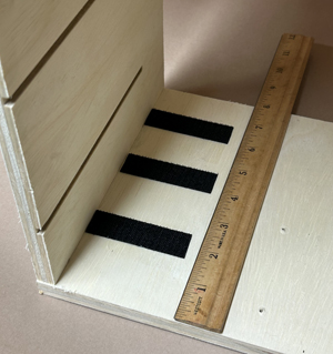
- Velcro hook & loop tape, self-adhesive, normal strength. (The high-strength stuff can get annoyingly hard to unmate).
- Anderson PowerPole Connectors (the 15-45 style, with both red and black housings), or whatever connector system you prefer to use for your equipment, for #18 wire. The best prices are typically at Powerwerx (see the link in "Wire" directly above), but on occasion Impulse Electronics has a 10% off sale that is a decent bargain. Also, get a PowerPole crimper if you don't already have one: PowerPoles are the modern standard for power connections, and investing in a crimper will ensure you get good connections. Note that suitable crimpers are sold by several vendors at similar prices.
A Note about the PowerPole 15-45 series contacts: The naming convention (e.g., 15A, 30A, 45A) confuses most customers into thinking that is the contact's current rating: IT IS NOT. All sizes of the 15-45 series contacts are rated the same, 55 Amps when used as a single connector! Their ultimate current capacity depends on the wire used, NOT the contact size.
- Two minor electronic components:
- One 22k (or 21k) Ohm 1/4 Watt resistor. Used to modify the HP Power Supply. These cost pennies, Mouser has them.
- One Littelfuse Polyfuse #30R185UU. This is a self-resetting thermal fuse that protects the wiring from a short on the battery terminals. It is rated at a 1.85 Ampere hold current, at a maximum of 30 volts. $0.62 at Mouser. You can use a 3 or 5 Amp fuse instead, but these will not self-reset when the fault is cleared.
- A couple of wood screws.
- Did I miss anything???
|
|
B. Prepare the Components
In this section, we preassemble and prepare some items for their final installation.
| B.1 |
Prepare HP Power Supply
|
For this step, you will need:
- The HP power supply
- The 22k Ohm 1/4 Watt resistor, and a 1-1/4" piece of small insulated wire (#18 is OK but large. #24 is OK, like a bit of CAT5 wire). This enables the power supply's voltage output.
- One foot of #12 AWG zip cord (or red and black #12 stranded copper wire, each a foot long. These instructions assume you have zip cord). This connects the power supply to the fuse box and Ground-bus.
- A few inches of Velcro Loop tape, or thick self-adhesive felt. This insulates the (bare metal) voltage sources on the power supply.
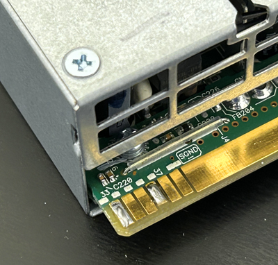
- Identify the soldering locations: Looking at the rear of the power supply, with the power supply top up (the six small gold contacts are on the left), note the FIRST, FOURTH and FIFTH small contacts. Note that the fourth contact is a bit shorter than the others. The resistor goes between the fourth and fifth contacts.
- Prepare the 22k Ohm resistor by bending one wire lead down over the top, so both leads point in the same direction. Then bend both the wire leads at a right angle to fit onto the two contacts you noted above. Cut the wire leads to about 1/4" long. See the photo.
- Tin (apply a thin later of solder to) the three contacts you noted.
- Using the needle-nose pliers, hold the resistor in place while soldering one wire lead to one of the contacts.
- Correct the positioning of the resistor's other wire lead if needed, then solder it to the other contact. Study the second image here carefully to verify you have installed the resistor on the correct contacts.
- Strip about 1/4" of the insulation from each end of the 1.25" piece of thin wire, bend the ends at right angle so it looks like a staple, then solder one end to the first contact.
- Now solder the other end of the 'staple' to the very large and wide power supply contact, as shown in the photo. Check your work so far carefully for good soldering.
- Separate about 1-1/4 inches of one end of the #12 zip cord wires, and strip them about 1-1/8".
- Twist each wire's strands together, then tin the wires heavily.
- Tin the top gold contact areas on the power supply rear edge connector. See the image showing the tinned wires and supply contacts.
- Using a hot soldering iron, solder the red wire to the right side (looking at the rear) contact area.
-
- Use a clip or clamp to hold the wire in place firmly against the contact surface - it will get very hot! - and be sure the bare wires won't touch each other after soldering. Take a look at the image to see how the red and black wires split apart and go to their separate sides of the power supply contact area
- Start soldering at the tip of the wire and, while adding solder generously, move towards the unstripped area of the wire. THIS MAY GO SLOWLY, as there is a lot of heat needed and a lot of surface to heat up.
- It can be helpful to get a large blob of melted solder on the soldering iron tip, as the mass of that blob will help transfer heat.
- Wait for things to cool a bit, then repeat for the black wire. See the image for what you want as the end result.
- IF YOU CAN'T get the solder to melt enough, get a more powerful soldering iron or, if you're really careful, use a soldering gun.
- Carefully inspect the soldering work. The wires should make good contact with the power supply contact area, and the red and black sides don't touch each other. There should be solder fillets between the circuit board and both sides of the wire.
- After you are satisfied all is well, plug in the HP power supply using an IEC cord, verify the green power LED in front (near the fan) is ON. Measure the output voltage, which should be around 12.3 Volts DC. Make sure the RED wire has the POSITIVE (+) Voltage.
- If all is correct, cover both the top and bottom of the rear power supply connector area with velcro loop tape. You must insulate all exposed metal, since this power supply can deliver quite a lot of energy if a short-circuit were to occur.
- Separate about 4 inches of the other end of the red/black zip cord, and strip the end of the red wire 1/4 inch. Twist the wire strands together and crimp to the red wire a ring terminal for #10 hardware.
This completes the HP Power Supply preparation.
|
This photo shows the first and fourth contacts, tinned with solder.
This photo shows the 22k Ohm resistor and the jumper wire (orange) soldered in place. 
The large power contacts are tinned, and the #12 AWG wire is tinned and bent as needed. 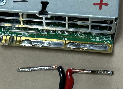
The heavy wires are soldered in place. 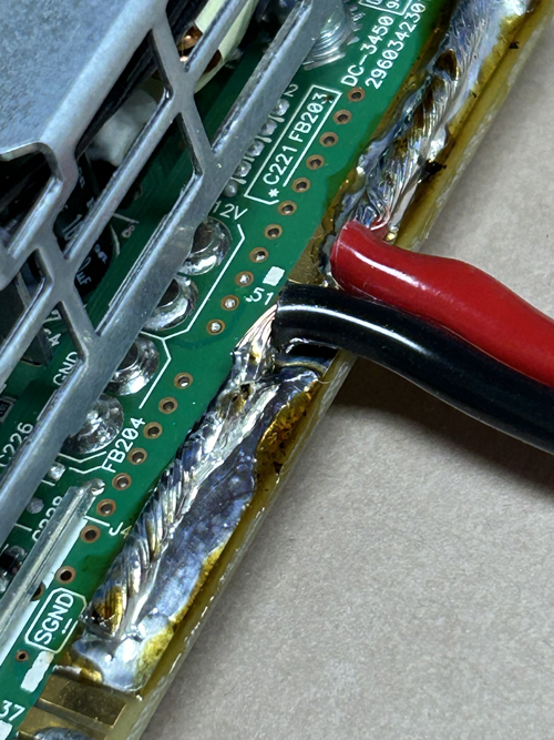
The power contacts must be fully insulated, both top and bottom! Electrical tape is insufficient, use velcro loop or adhesive felt. 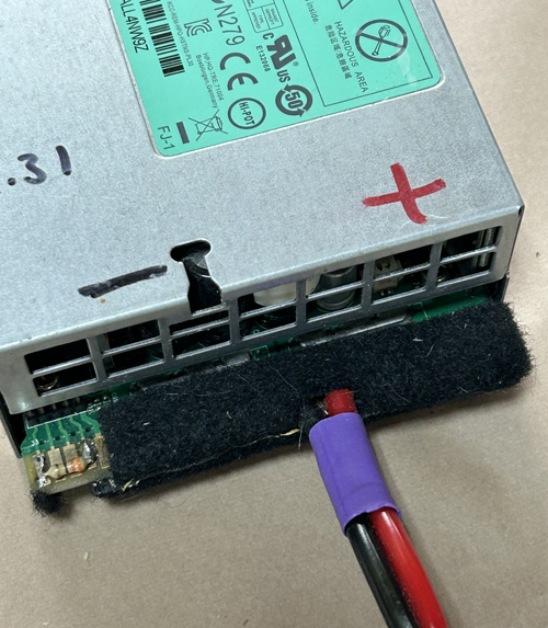
|
| B.2 |
Assemble the Power Switch Circuit
|
For this step, you will need:
- The full-wave diode bridge
- The 10 Watt resistor
- A few pieces of assorted-color #18 hook-up wire. (Colors may be substituted if needed, but be consistent in usage).
- The soldering iron and solder
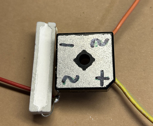
- Note that the full-wave bridge package consists of four diodes, arranged in a square, cathode-to-anode, with a wire coming out at each intersection. There are four wires: two "AC" wires (each using a "~" symbol), one "+" (plus) wire, and one "-" (minus) wire.
- Identify the four wires of the full-wave bridge: First find the "+" (plus) and one of the "~" (AC) wires (marked on the device), then match these up with the image. Mark each of the terminals somehow, such as with a Sharpie marker on the bottom. If you used a part different from the recommendation, consult the manufacturer's data sheet.
- Connect the resistor between one of the "~" (AC) lead wires and the "-" (minus) lead wire. Wrap the resistor wire leads half a turn around the full-wave bridge wires. Try to keep the resistor wire leads even in length and without any excess. Solder the resistor to the "-" (minus) wire ONLY for now.
- Cut a 4-inch piece of orange wire and strip one end 1/2 inch. Twist the strands together and wrap the end around the "~" (AC) lead wire that is NOT connected to the resistor. Solder the wire to the bridge.
- Cut a 4-inch piece of yellow wire and strip one end 1/2 inch. Twist the strands together and wrap the end around the "+" (plus) lead wire. Solder the wire to the bridge.
- Cut a 3-inch piece of red wire and strip 1/2 inch from one end. Twist the strands together and wrap the end around the "~" (AC) lead wire that is also connected to the resistor. Solder the wire and resistor lead to the bridge.
- Strip the free ends of the red, pink and orange wires 1/4 inch. On the orange wire, twist the wire strands together and crimp on a 1/4 inch crimp-on quick-disconnect terminal.
This completes the Power Switch Circuit preparation.
|
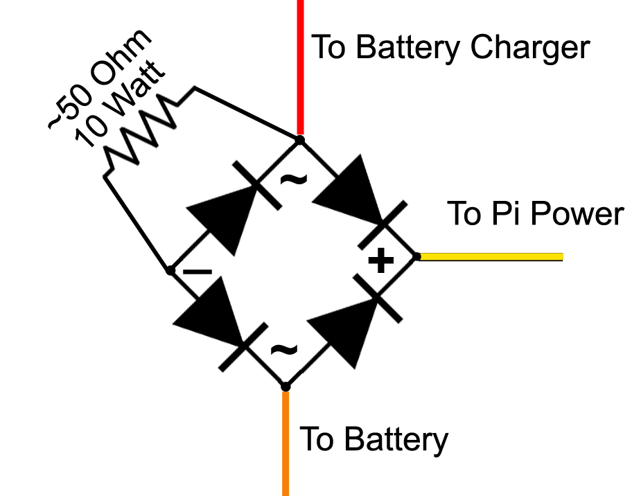
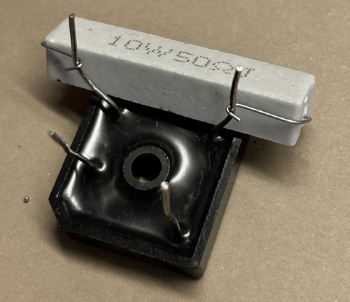
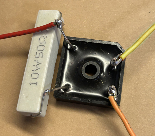
Be sure to verify YOUR bridge terminal assignments (~, +, -).
Don't rely on this photo.
|
| B.3 |
Assemble the Battery Wire
|
For this step, you will need:
- Two 22-inch pieces of #18 hookup wire, one orange and one black.
- The Polyfuse (or other fuse device). NOTE: Your Polyfuse may be rectangular.
- One 1/4" female crimp-on quick-disconnect contact suitable for #18 wire.
- Two 3/16" female crimp-on quick-disconnect contacts suitable for #18 wire.
- Strip both ends of both the orange and black wires to 1/4 inch.
- To one end of the black wire, crimp one 3/16" female crimp-on quick-disconnect contact.
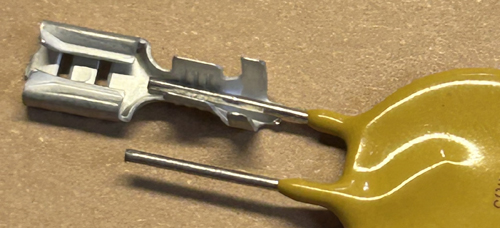
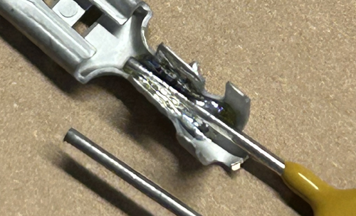
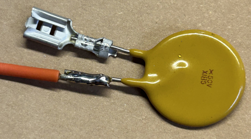
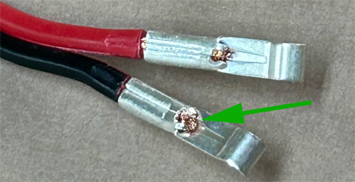
- Solder to one of the Polyfuse's leads a 3/16" female quick-disconnect contact. Note that the Polyfuse wire is too small to crimp properly - it is necessary to solder the polyfuse wire lead to the contact. The images show the wire lead laying on the contact, then the contact after soldering. In the third image, note that the 'ears' of the quick-disconnect contact have been bent down over the soldered wire lead.
- Solder one end of the orange wire to the other wire lead of the Polyfuse.
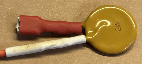
- Slip a suitable (1/8"-3/16") piece of heat-shrink tubing over the orange wire and heat it to completely cover and insulate the solder connection to the Polyfuse. Repeat this for the other lead wire of the polyfuse with the 3/16" contact (1/4" heat shrink works well here). Since this is the positive (+) connection to the battery, take extra care to ensure that no bare metal is exposed. The fourth image shows a fully-insulated Polyfuse.
- To the other end of the orange wire, crimp a 1/4" female crimp-on quick-disconnect contact.
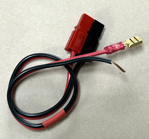
You should end up with two wires, the black one that connects to the battery (-) negative terminal and to the upper Wago Lever Nut, as well as the orange wire that connects to the battery (+) positive terminal and one of the male 1/4" quick-disconnects on the back of the Control Panel.
NOTE: Avoid adding heat-shrink over the PolyFuse: It is a thermal device, and its performance depends on the body of the device being in free air. Don't cover it with heat shrink tubing, tape, or anything else. This completes the Battery Wire preparation.
|
|
| B.4 |
Assemble the Radio Power Wires
|
In this step, you will assemble the power cords that are connected to your node radios. We give instructions for one, using PowerPole contacts. You may use any contact system you prefer, but our loaner radios all use PowerPoles. Regardless of the connectors you use, consider making three of then now, so you have them when you add radios in the future.
For this step, you will need:
- One 12-inch piece of #18 (or #16) red/black paired Zip Cord.
- Two PowerPole contacts suitable for #18 wire. (We use the 15A contacts successfully for #18 and #16).
- One set (Red/Black) PowerPole connector bodies.
- One 1/4" female crimp-on quick-disconnect contact suitable for #18 wire.
- Separate about an inch of one end of the Zip Cord, and strip each wire to 1/4 inch.
- Crimp a PowerPole Contact to the red and black wires. The top image shows two good crimps: A small bit of wire showing at the end of the crimp barrel (arrow), a full crimp, and no (or almost no) copper showing on the insulation side of the barrel.
- Insert each contact into the correct color housing.
- Arrange the red and black housings as shown and slide them together. The black housing slides from the rear towards the front of the red housing. Getting this orientation correct is important!
- Strip the other end of the red wire to 1/4 inch and crimp on a 1/4" female crimp-on quick-disconnect terminal.
Repeat for as many wires as you want.
This completes the Radio Power Wire preparation.
|
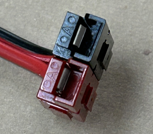
The image above shows the SPROING Standard PowerPole Orientation. With the metal contacts UP, Red is on the LEFT.
 |
| B.5 |
Prepare and attach the USB-C cable
|
In this step, you will ready the USB-C to USB-A Raspberry Pi power cable and attach it to the DROK Pi Supply, which uses screw-clamp terminals.
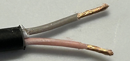
- Cut the USB-C cable so it is about five to seven inches long. You'll need about an inch of wire on the USB-A (rectangular plug) side, so don't cut that end too short.
- Strip a half-inch of the outer wire insulation off the USB-A end and identify which two wires are Power and Ground (usually pink or red for (+) and black or gray for (-), with blue or green and white for data). VERIFY their actual function TO BE SURE (never a bad idea):
- Strip the ends of all four wires from the USB-A plug a bit.
- Connect the USB-A to a wall-wart USB power supply.
- Using your multimeter on DC Volts, touch the probes to the wires until you measure around 5 volts DC. Be sure the reading is not showing a negative voltage - if it is, reverse the probes on the wires. Feeding -5 volts to your Pi is not good.
- With the power wires and their polarity identified, write down which wire is which.
- Place a one-inch piece of heat-shrink tubing over the USB-C wire.
- Strip off about 3/4" of the outer insulation from the USB-C wire.
- Strip about 3/16" of the wire insulation from the (+) 5 v and (-) ground wires you identified and twist the bare strands on themselves so there are no stray wires sticking out.
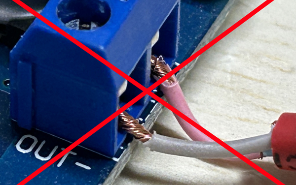
- Back off the clamp screws on the output side of the DROK Pi Power Supply using a small flat-blade screwdriver.
- Carefully insert the wires into the (+) and (-) terminal on the power supply output side, then tighten the screws. Tug on each wire to verify you have a good connection; if it comes out, do it again. Sometimes doubling up the wire end (strip 3/8", then fold it back so you have a 3/16" double-wire) can help.
If any bare wire is visible from the screw clamp terminals, remove the wires, cut them shorter, and reinstall them.
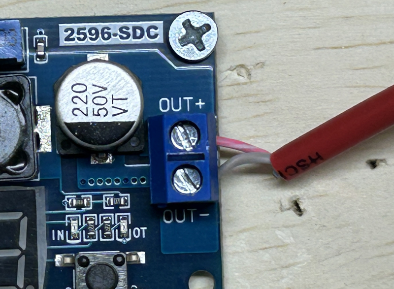
- Slide the heat-shrink tubing as far towards the bare wire end of the cable as possible, then apply heat to shrink it in place.
This completes Component Preparation.
|
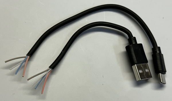
Cut USB cable.
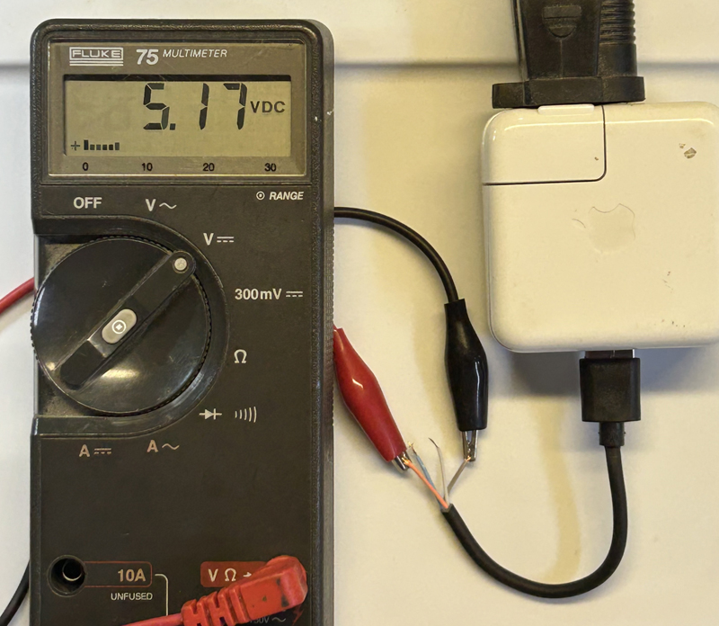
Testing the USB-A side to find (+) and (-) wires, here pink and gray.
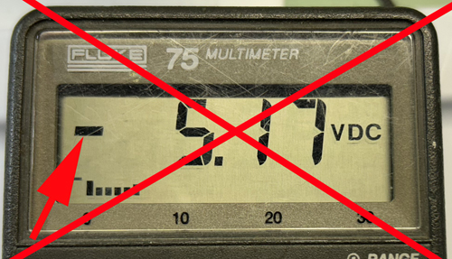
The above image shows a negative voltage - reverse the wires, as this is bad.
Nice, cleanly-twisted wires. Data wires cut away.
Too much wire showing.
Perfect!
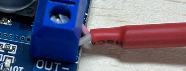
Heat-shrink in place and shrunk.
|
C. Install the Components
In this section, we install the various components into their installation position.
| C.2 |
Install the Battery
|
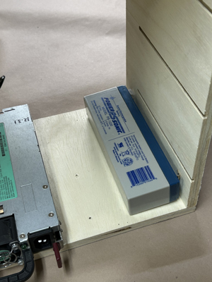
Using velcro, attach the Backup Battery to the bottom of the Nodebox on the right side. The electrical terminals should be placed against the wooden box side, with the positive (+) terminal towards the rear of the NodeBox. The battery terminals should be away from the NodeBox bottom.
|
|
| C.3 |
Install the Fuse Box
|
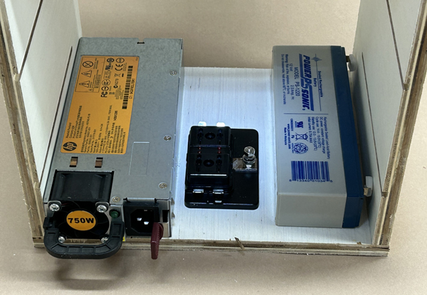
Remove and discard the clear plastic cover of the Fuse Box (It just gets in the way). Position the Fuse Box evenly spaced between the HP Power Supply and the Backup Battery, with the #10 connection stud terminal towards the battery. Use two one-inch wood screws in the holes on the fuse box to fasten it to the wood bottom. CAUTION: Longer screws will poke out the bottom and be an injury hazard.
Once the fusebox is installed, connect the HP Power Supply's AC power cable to the sicket in the front of the supply, then route it from the front of the box towards the rear, holding it firmly between the power supply and the fusebox with cable clips (or something) as shown in the lower image of step D.2 below. You want the AC cord to be away from the fusebox power input stud.
|
|
| C.4 |
Install the Pi Power Supply
|
Using small wood screws with spacers, or a generous amount of velcro, fasten the Pi Power Supply to the right side of the NodeBox Top. The USB-C cable previously attached (not shown here) should face the rear of the box.
|
|
| C.5 |
Install the Battery Charger Supply
|
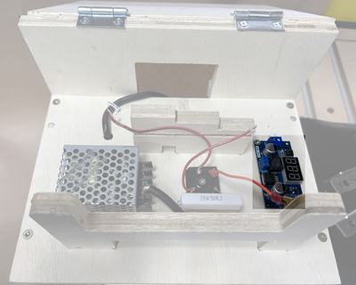
NOTE: The Meanwell is shown installed, the DROK 200446 goes in the same place.
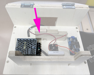
- MEANWELL RS-15-15: Using two M3 x 13mm machine screws, install the Meanwell RS-15-15 to the left side of the NodeBox top using holes "A". The terminal screws of the Meanwell MUST be located in the area shown in the image (arrow): This allows the small Pi holding plate (not shown) to provide additional protection against accidental contact with the 110 VAC power input terminals.
THIS IS A SAFETY ITEM, BE TOTALLY CERTAIN.
The screws are just long enough to reach, and are installed from the inside of the NodeBox upwards through the holes provided. Use care to line up the holes properly.
(NOTE: Holes "B" are sized for the Meanwell RS-25-xx series supplies, which can also be used here).
- DROK 200446: Using two M3 x 13mm machine screws, mount the DROK 200446 to the left side of the NodeBox top using two diagonally-opposed holes "C" - doesn't matter which two. The DROK is supplied with threaded standoffs: attach them as shown, then attach the board to the top of the NodeBox.
The screws are just long enough to reach, and are installed from the inside of the NodeBox upwards through the holes provided. Use care to line up the holes properly.
The output terminals should be facing the Pi Power Supply.
|
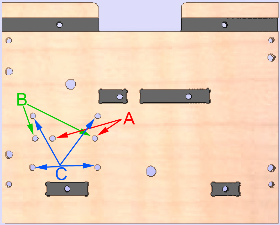
Use Holes "A" for the Meanwell RS-15-15. Use Holes "C" for the DROK 200446. (Holes "B" are for the Meanwell RS-25-xx series, which can be a reasonable substitute).Below the DROK 200446 is shown.


The above below shows the output end of the DROK 200446. The smaller standoffs support the top plastic cover, the longer standoffs go between the board and the wood top. You can also see the optional green button covers installed. All these parts are included with the kit as sold by Amazon.
|
| C.6 |
Install the Power Switch Circuit
|
Using a 1-1/4" #8 wood screw, fasten the assembled Power Switch Circuit in the position shown, using the hole in the center of the full-wave bridge. Do not overtighten the screw, it can break the full-wave bridge. The Red wire should be located towards the left when facing the front of the NodeBox. The resistor can be towards the front or the back.
|
|
| C.7 |
Install the Control Panel
|
Using two or four #6 x 1/2" wood screws, fasten the Control Panel into the front opening as shown.
|

|
| C.8 |
Fasten the Pi to its Holder
|
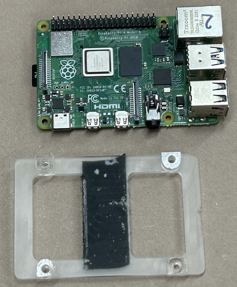
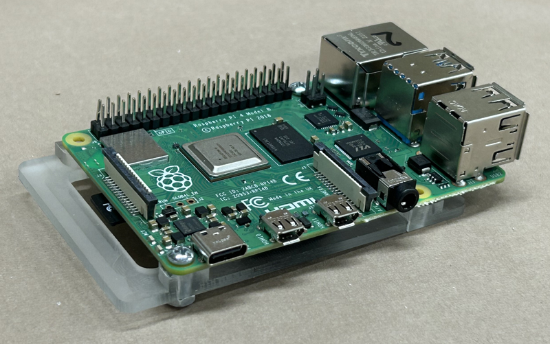
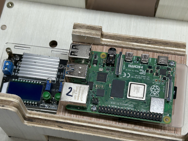
- Using an N2IRZ TNC/Pi Holder, mount the Raspberry Pi to the holder using two #4 x 3/8" machine screws and nuts. The completely flat side of the plastic Pi Holder faces away from the Raspberry Pi.
- Place a strip of velcro along the 3/4-inch-wide cross member of the TNC/Pi holder, a matching strip on the wooden Pi plate, and fasten the Pi plus Holder assembly to the wooden Pi Plate. (Alternatively, use short wood screws and thin spacers to fasten the Pi directly to the wooden Pi Plate.)
- Temporarily slide the wooden pi plate into place above the power switch circuit, the place the Raspberry Pi onto the Pi Plate.
DO NOT Connect the Pi to anything just yet!
This completes the Component Installation, now we'll finalize the wiring.
|
|
D. Wire the Components
In this section, we install the wiring between the various components.
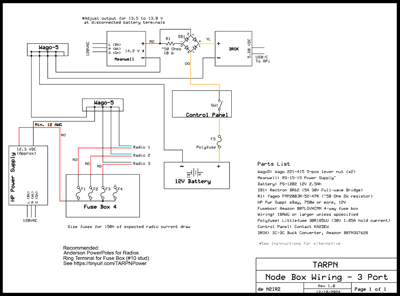
Here is the N2IRZ 3-Port NodeBox Wiring Schematic. Click to load the PDF.
| D.1 |
Using Wago Lever Nut Connectors
|
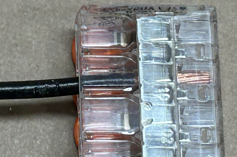
Before we start, be sure to use the Wago connectors properly.
- To unlock the connector, flip the orange lever up.
- Wires from 24 AGW to 10 AWG can be used. Smaller or larger wires must not be used.
- Only one wire per opening.
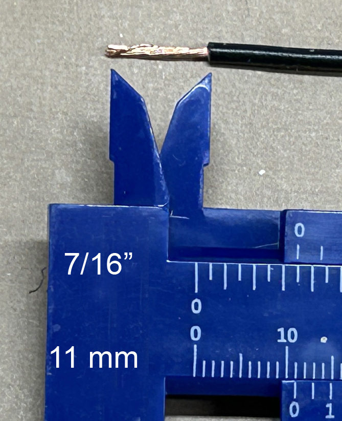
- Strip wires 11 mm (7/16") - there is a strip gage on the side of the connector.
- Insert the stripped wire fully, then flip the lever down. Tug on the wire to check it is secure.
- The bottom is clear to check proper insertion and installation.
|
|
| D.2 |
Connect the black wires
|
Connect the several #18 (or #16) black wires as follows:
- A 5" piece from the Meanwell or DROK 200446 (-) DC Output terminal (On the Meanwell, temporarily remove and retain the small clear plastic cover over the Meanwell's terminals. It gets reinstalled in Step D.6a #11) to a Wago Lever Nut (the 'upper' nut). Put this lever nut behind the central Pi support bracket, near the opening in the rear bracket between the top hinges. On the Meanwell, loosen the screw a few turns, place the stripped wire under the square clamp pad, then tighten the screw firmly. This can get a bit fiddly, be patient.
- A 6" piece from the (-) DC Input side of the Pi Power Supply to the upper nut.
- A 12" piece from the upper nut to a second ('lower') Lever Nut placed near the HP Power Supply. (If you have some heavier stranded wire, such as #16 or #14, use that here instead).
- Connect the black Battery wire to the upper Lever Nut, and then to the negative (-) battery terminal.
- Strip the #12 black wire from the HP Power Supply and connect it to the lower Lever Nut.
- Strip the black wire(s) on the Radio Power Wire(s) and connect it/them to the lower Lever Nut.
- If using the DROK 200446: A 6" piece from the (-) DC Input side of the DROK 200446 to the upper Lever Nut. (The image seems to point to the red wire, but this instruction is for the black wire)
You should have four wires connected to the upper Lever Nut and two to five wires connected to the lower Lever Nut.
|
The numbered steps correspond to the numbers in the images

 |
| D.3 |
Connect the Fusebox
|
- Connect the red #12 wire from the HP Power Supply (it should have a ring terminal installed) to the stud on the fuse box. Route the wire as shown. Tighten the nut securely.
- Connect each red Radio wire to an empty quick-connect terminal on the fuse box. Insert a suitable fuse for the terminal - Check the radio's installation manual for the correct fuse size to use.
Pro Tip: Label each PowerPole end with the radio model or fuse value, and tape some spare fuses to the box somewhere nearby.
|
The numbered steps correspond to the numbers in the images

|
| D.4 |
Connect the Power Switch Circuit
|
Connect the three Power Switch Circuit wires as follows. If necessary, slide off the Raspberry Pi, Pi Holder, and Pi Plate and set them aside.
- Connect the Red wire to the (+) DC Output of the Battery Charge Supply (Meanwell or DROK Boost-Buck). The Red wire comes from the full-wave bridge AC (~) terminal that is also connected to one end of the resistor.
Both DC Output terminals should be wired now.
- Connect the Orange wire to one of the 1/4" quick-connect male terminals on the back of the Control Panel Board. The Orange wire comes from the full-wave bridge AC (~) terminal, and should have a 1/4" female quick-connect terminal crimped on.
- Connect the Yellow wire to the positive (+) DC Input terminal of the Pi Power Supply.
Both DC Input terminals should be wired now.
The Power Switch Circuit should be completely wired at this point.
|
The numbered steps correspond to the numbers in the images
 |
| D.5 |
Connect the Control Panel Battery Circuit
|
- Connect the battery wire (assembled in Step B.3) to the un-connected 1/4" quick-connect male terminal on the back of the Control Panel Board.
- Turn the Control Panel battery switch OFF (0).
- Route the Battery Wire to the rear of the node box, out the opening between the hinges, and down to the backup battery. There is a small slot cut into the center Pi holder bracket for this wire, or route around the bracket. Don't run the wire over the bracket!
- Verifying the battery switch* on the Control panel is off, connect the other end of the battery cable to the battery (+) positive terminal. Use care, as the 3/16" quick-connect terminal may be a bit tight, and the wire lead of the PolyFuse is fragile.
- TEST: Briefly turn the Control Panel battery switch* ON. The Pi Power Supply should show some life. Turn the battery switch OFF.
- *I use a jumper instead of a switch (it is cheaper), same effect.
|


 |
| D.6a |
Connect the MEANWELL Battery Charge Supply
|
These instructions are for the MEANWELL version. The DROK 200446 version (PREFERRED)
is further below.
This step connects the AC power cord to the Meanwell's AC inputs.
- Cut the IEC connector off the Meanwell's power cord (leave the three-prong standard AC plug on).
- Route the cut end of the wire down through hole "X" to the box interior, then up (out) through hole "Z". Allow yourself about 8 inches of wire sticking up through the top at hole "Z".
- Strip off about an inch of the outer insulation, then strip the three inner wires to 1/4".
- Most IEC cords use the color standard GREEN is GROUND, WHITE is NEUTRAL and BLACK is HOT/LINE. If your cord uses these standards, continue to Step 4.
- If your cord uses a different standard, you MUST determine which wire does what, and doing this incorrectly could expose you to a lethal shock hazard. So do this carefully. If you are the LEAST BIT unsure, get experienced electrical help here. YOUR LIFE DEPENDS ON IT.
- Using a multimeter on the Ohms setting, verify that it reads around ZERO Ohms when the two test leads are connected together, and an open circuit (perhaps "OL") when the leads are not touching each other.
- If your meter passes the above test, connect one test lead to the AC prong labeled "G" in the image. Connect the other lead to each of the three exposed wires until you get a Zero reading. Write down the wire color and that it is GROUND.
- Connect one test lead to the AC prong labeled "N" in the image. Connect the other lead to one of the two remaining exposed wires until you get a Zero reading. Write down the wire color and that it is NEUTRAL.
- Connect one test lead to the AC prong labeled "L" in the image. Connect the other lead to the one remaining exposed wire and verify you get a Zero reading. Write down the wire color and that it is LINE.
- Now touch the two meter leads together again and verify that it reads around ZERO Ohms.
- IF ANY BIT OF THE TESTS ABOVE FAILS OR SEEMS 'ODD', STOP AND GET COMPETENT ELECTRICAL HELP.
- Continue to wire the meanwell's AC inputs. (It may be easier to connect all three wires at the same time)
- Connect the GROUND wire to the Meanwell's GROUND Input Terminal: Loosen the screw a few turns, place the stripped wire under the square nut, then tighten the screw firmly.
- Connect the NEUTRAL wire to the Meanwell's N Input Terminal: Loosen the screw a few turns, place the stripped wire under the square nut, then tighten the screw firmly.
- Connect the LINE wire to the Meanwell's L Input Terminal: Loosen the screw a few turns, place the stripped wire under the square nut, then tighten the screw firmly.
- Firmly attach a wire tie to the AC cable about 3 inches from where the wires connect to the Meanwell, and trim the wire tie excess.
- Gently pull the AC wire into the box interior until the wire tie stops its movement.
- Now gently pull the AC cord up through Hole "X" until there is no excess AC wire inside the NodeBox interior.
- Route the AC plug though the opening at the rear of the NodeBox, between the hinges, to the back of the box.
- Reinstall the small clear plastic cover over the Meanwell's terminals.
- Connect the Meanwell's power cord to an AC wall outlet.
- Measure the Meanwell's DC output, and adjust the voltage using a Phillips screwdriver (Use gentle force on the adjustment!) until it reads as close as possible to 14.20 volts DC an a voltmeter.
(This is the battery charging voltage, minus the 0.7 volt drop across the full-wave bridge diode. Batteries in 'float' usage should get 13.5 to 13.8 volts to avoid battery damage).
- Unplug the AC cord from the outlet.
|
Images Pending

 |
| D.6b |
Connect the DROK 200446 Battery Charge Supply
|
These instructions are for the DROK 200446 version. The Meanwell version is above.
This step connected the DC power input to the DROK 200446 battery charger supply.
- Cut a piece of RED wire to 20 inches.
- To one end, strip the wire and crimp a 1/4" female quick-connect to it.
- Strip the other end 3/16" and connect it to the positive (+) DC INPUT of the DROK 200446 using the screw clamp terminal.
- Route the wire to the rear of the NodeBox and down to the Fuse Box.
- Connect it to a unused fusebox quick-connect tab, and install a 5 Amp fuse for that position.
- Verify that the negative (-) DC INPUT of the DROK 200446 was connected with black wire to the upper Wago nut in Step 7 of Section D2 above. (If it isn't, connect it now).
- Connect AC power to the HP Power Supply. The DROK 200446 should start up.
- Using a voltmeter connected to the DROK 200446 output terminals, adjust the voltage until it reads as close as possible to 14.20 volts DC.
(This is the battery charging voltage, minus the 0.7 volt drop across the full-wave bridge diode. Batteries in 'float' usage should get 13.5 to 13.8 volts to avoid battery damage). Don't count on the DROK voltage display to be accurate.
|


In the image below, we are adjusting the Constant Voltage (CV) potentiometer, not the Constant Current (CC) potentiometer. The CC pot should be at its maximum at all times - read the instructions for the DROK 200446. The necessary voltmeter is not shown here: Do NOT trust the DROK's voltage reading!
 |
| D.7 |
Adjust the Pi Power Supply
|
- Connect a voltmeter to the output screws on the Pi Power Supply
- Adjust the voltage using a small flat-blade screwdriver until the voltmeter reads as close to 5.20 volts as possible.
This is the voltage supply for the Raspberry Pi. which requires slightly more than 5 volts to operate error-free.
Do not rely on the power supply's voltage display as being accurate.
|
 |
| D.8 |
Connect the Control Panel to the Pi
|
In this step, we install the Raspberry Pi and connect it to the control panel.
- Reinstall the Raspberry Pi, on its holder, onto the Pi Plate and slide it all over the Power Switch Circuit. If using the Meanwell Power Supply, be certain the Pi Plate completely covers and hides the AC Power input terminals.
- Connect the 10-conductor ribbon cable to the male header on the Control Panel.
- Connect the other end of the ribbon cable to the Raspberry Pi:
- Count seven pins from the right (SD-Card-end) and mark the 7th pin with a sharpie marker.
- Count eight pins from the left (Ethernet-end) and mark the 8th pin with a sharpie marker.
- There should be five pins between the markings.
- Connect the ribbon cable to these five pins (and the five pins behind them in the second row).
- If the ribbon cable connector doesn't fit, you have two choices:
Add a 2x5 header extender ($1.50) to the ribbon cable connector, which will plug into the Pi easily, or
Cut the marked pins (and the pins behind them) off the Pi so the ribbon cable fits.
I advise against this radical, disfiguring surgery.
This completes the NodeBox wiring.
|
Images Pending
|
E. Some Operating Tips
Hints and tips on operating your node.
- Battery Switch: Leave the battery switch ON unless you have a reason to switch it off. This controls both battery charging (you want it to be continuously on charge) and availability of the battery to back up the Pi's power supply. The Pi really dislikes having its power switched off unexpectedly; this helps avoid that.
- Pi Shutdown: Shut down the Pi using any of these methods. Simply removing the power is to be avoided, as it can corrupt the microSD card, requiring the node to be re-built from scratch.
- Press and hold the SHUTDOWN switch on the control panel for about six seconds.
- Use the "tarpn shutdown" command in the Linux command window.
- Select "logout - shutdown" from the Pi's desktop 'raspberry' menu.
- After waiting about 30 seconds, and the green LED on the Pi shows no activity, remove power from the Pi. Switch the battery switch on the control panel OFF.
- Pi Reboot: You can reboot the node using the control panel's REBOOT button (hold it for about 6 seconds). However, it is often better to use the "tarpn kill" command, which restarts all tarpn software without a hard reboot of the Pi.
Rebooting can also use the "tarpn reboot" command in the Linux command window, or "logout - reboot" from the Pi's desktop 'raspberry' menu.
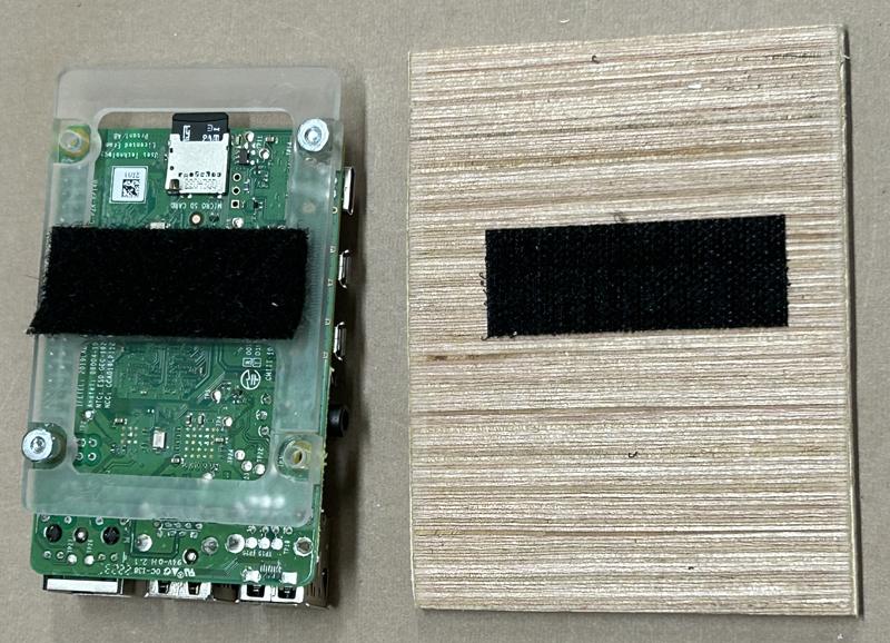
- Shelves: Use velcro to hold your radio and TNC on the NodeBox shelf. Don't glue or fasten the shelves permanently, as you'll want to slide them out sometimes for better access.
- Fuses: Keep a small supply of spare fuses handy, perhaps tape a small bag of them to the box somewhere.
- To Be Continued...
That's about all there is to say about it.
This website is maintained by Don Rotolo, N2IRZ. Contact me via the information on QRZ.COM
 .ORG - We're getting ready to move!