
Feel free to use any of the images on this page for publicity or articles! Commercial Use is Prohibited.
Note that some of these photos are of a pre-release version of the board.
If this is your first time building a kit, or need some guidance on soldering, please visit The Adafruit Guide to Excellent Soldering. Very highly recommended.
Of course, finding a neighbor, ham club member, or friend with electronics soldering experience is a great resource.
And, there's some great info on soldering at the TARPN website. Scroll down that page a bit to "soldering tips".
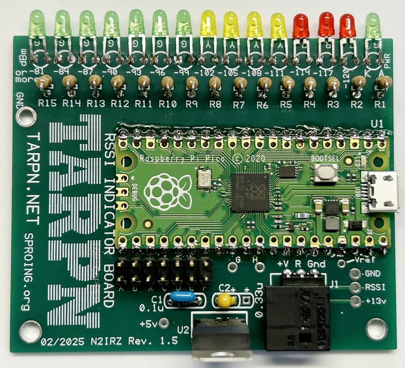
Please carefully inspect your kit to identify and verify each component. See the Assembly Instructions below for photos of each item.
| Qty | Item | Designation | Image |
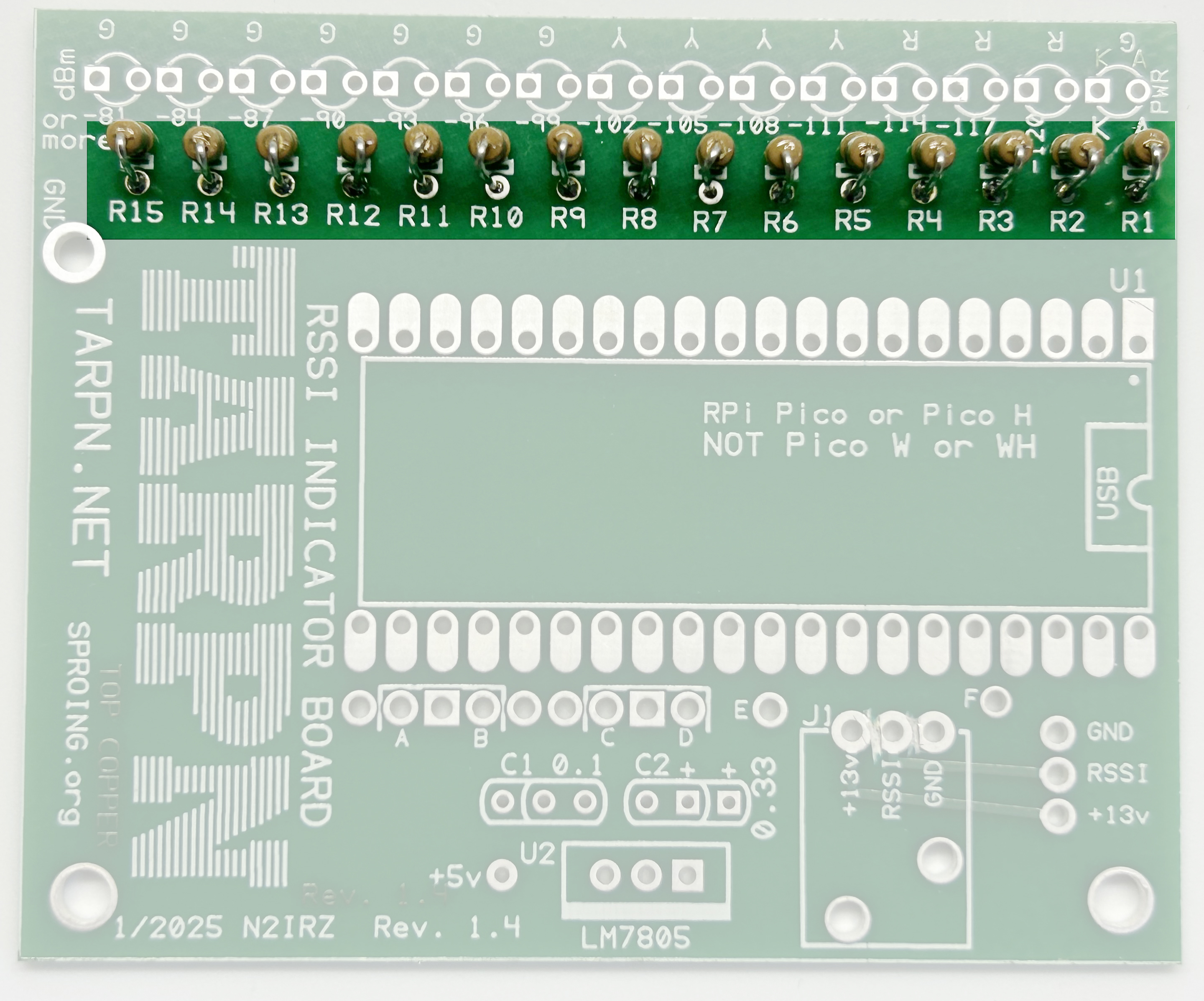
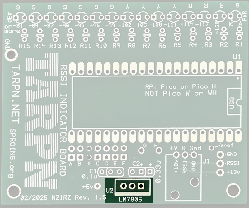
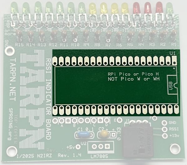
| 1 | N2IRZ RSSI Board PC board | Board |

|
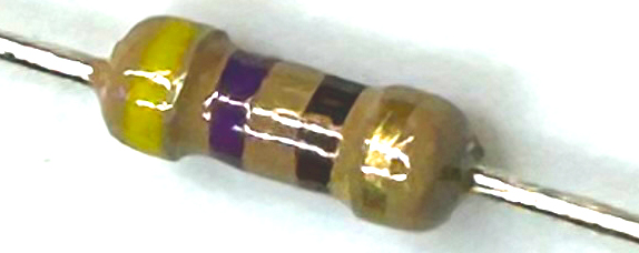
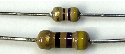
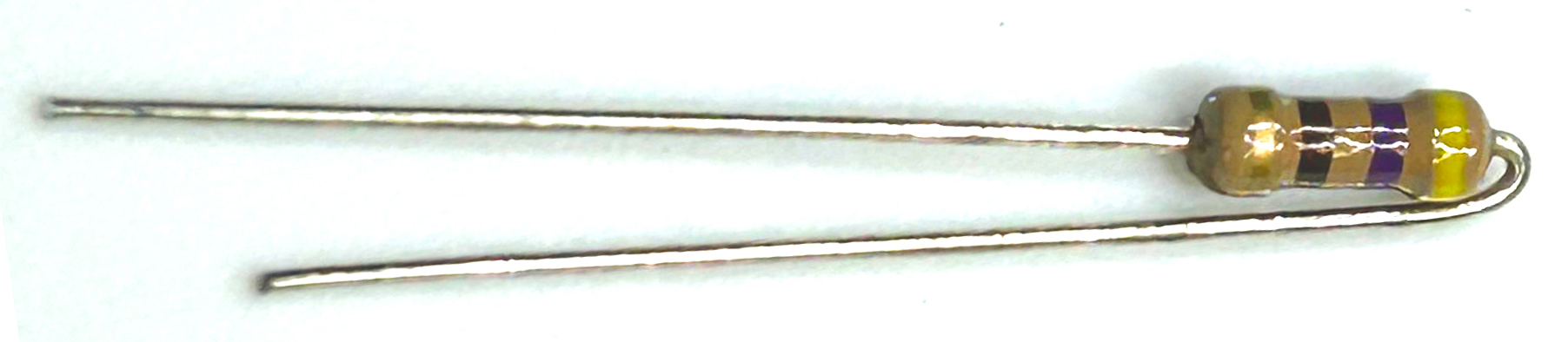
| 15 | 470 Ohm ¼ W resistors | R1-R15 |
|
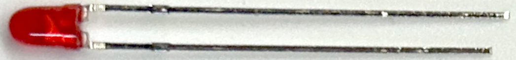
| 3 | Red LEDs, T-1, 2 mA | D2, D3, D4 |
|
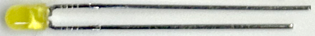
| 4 | Yellow LEDs, T-1, 2 mA | D5-D8 |
|
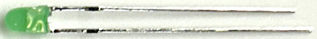
| 8 | Green LEDs, T-1, 2 mA | D1, D9-D15 |
|
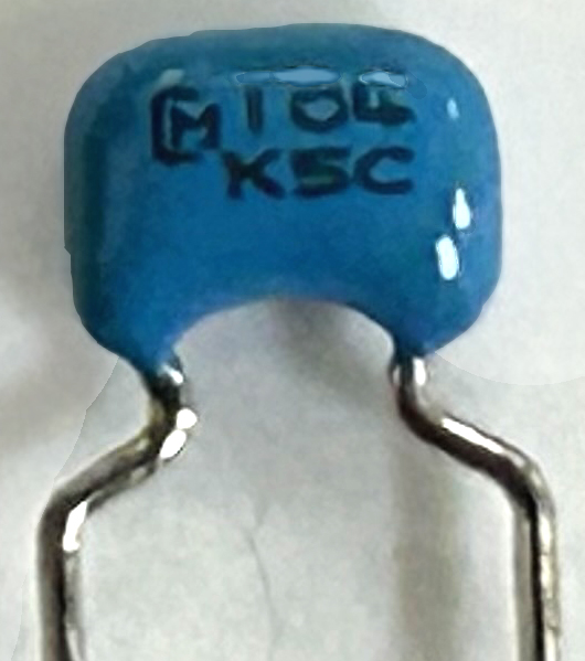
| 1 | 0.1 uF monolithic capacitor | C1 |
|
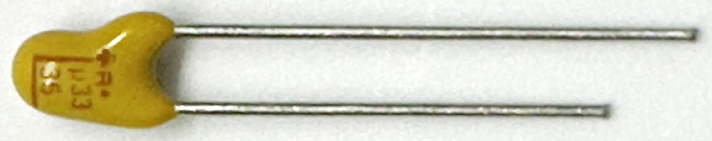
| 1 | 0.33 uF tantalum capacitor | C2 |
|
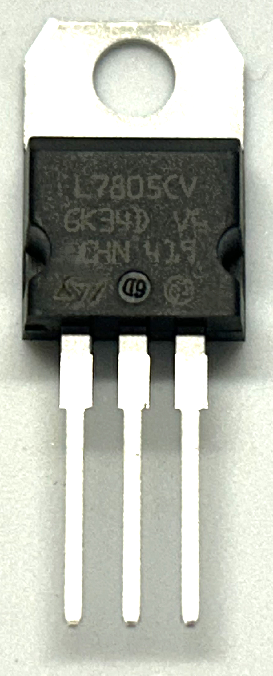
| 1 | LM7805 voltage regulator | U2 |
|
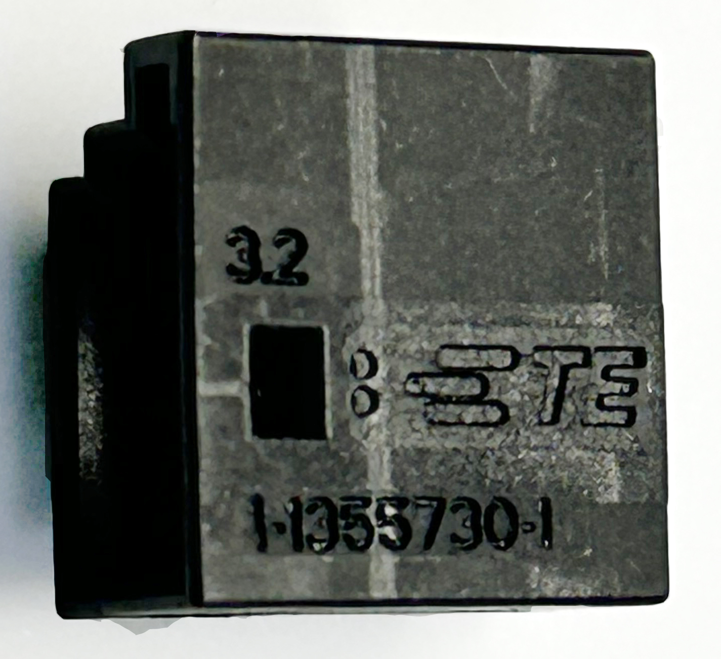
| 1 | 3-pin MQS Male header | J1 |
|
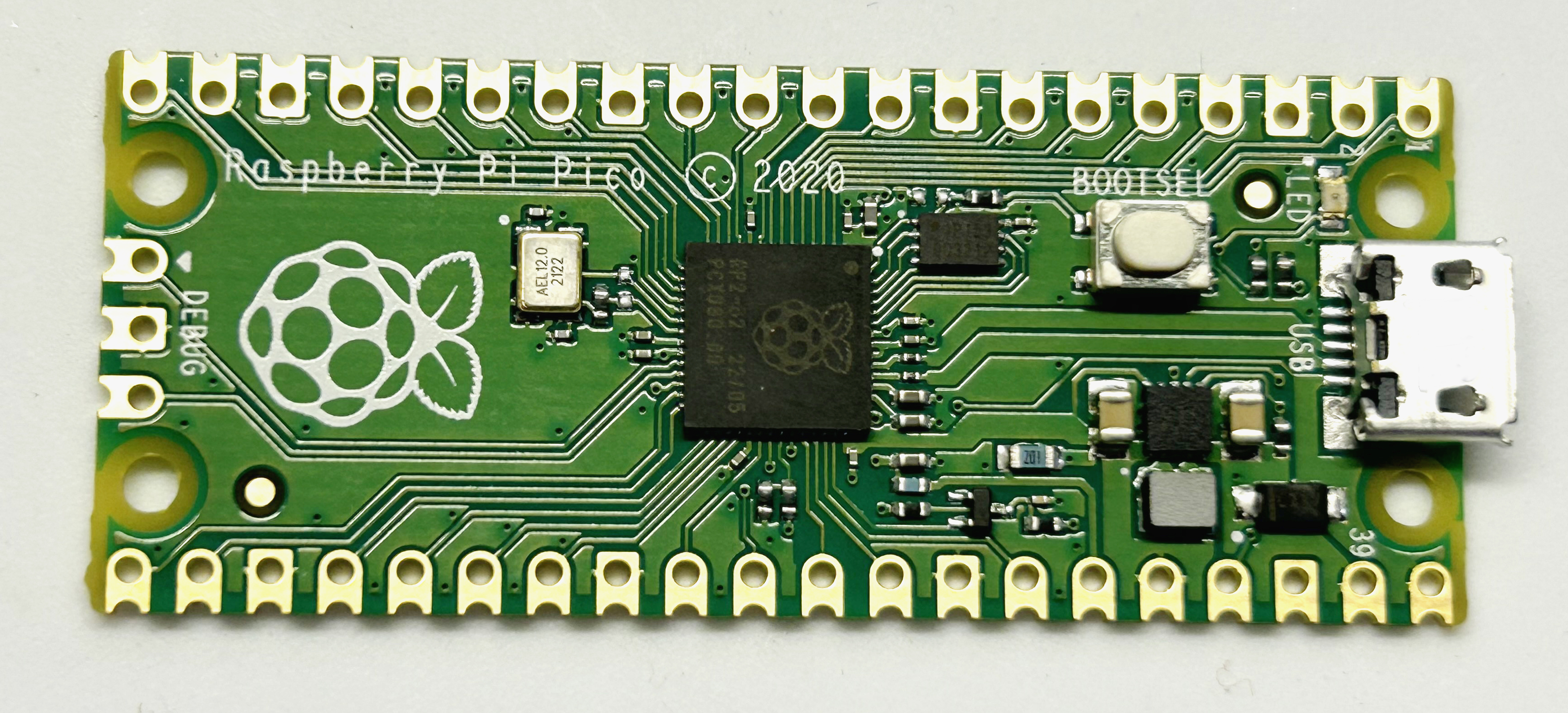
| 1 | Raspberry Pi Pico | U1. |
|
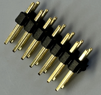
| 1 | 2x7 0.100" header | Header |
|
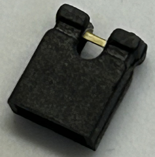
| 1 | 0.1" Berg Jumper | Jumper |
|
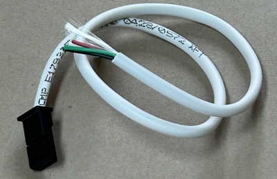
| 1 | Pre-crimped 3-wire MQS cable | Cable |
|
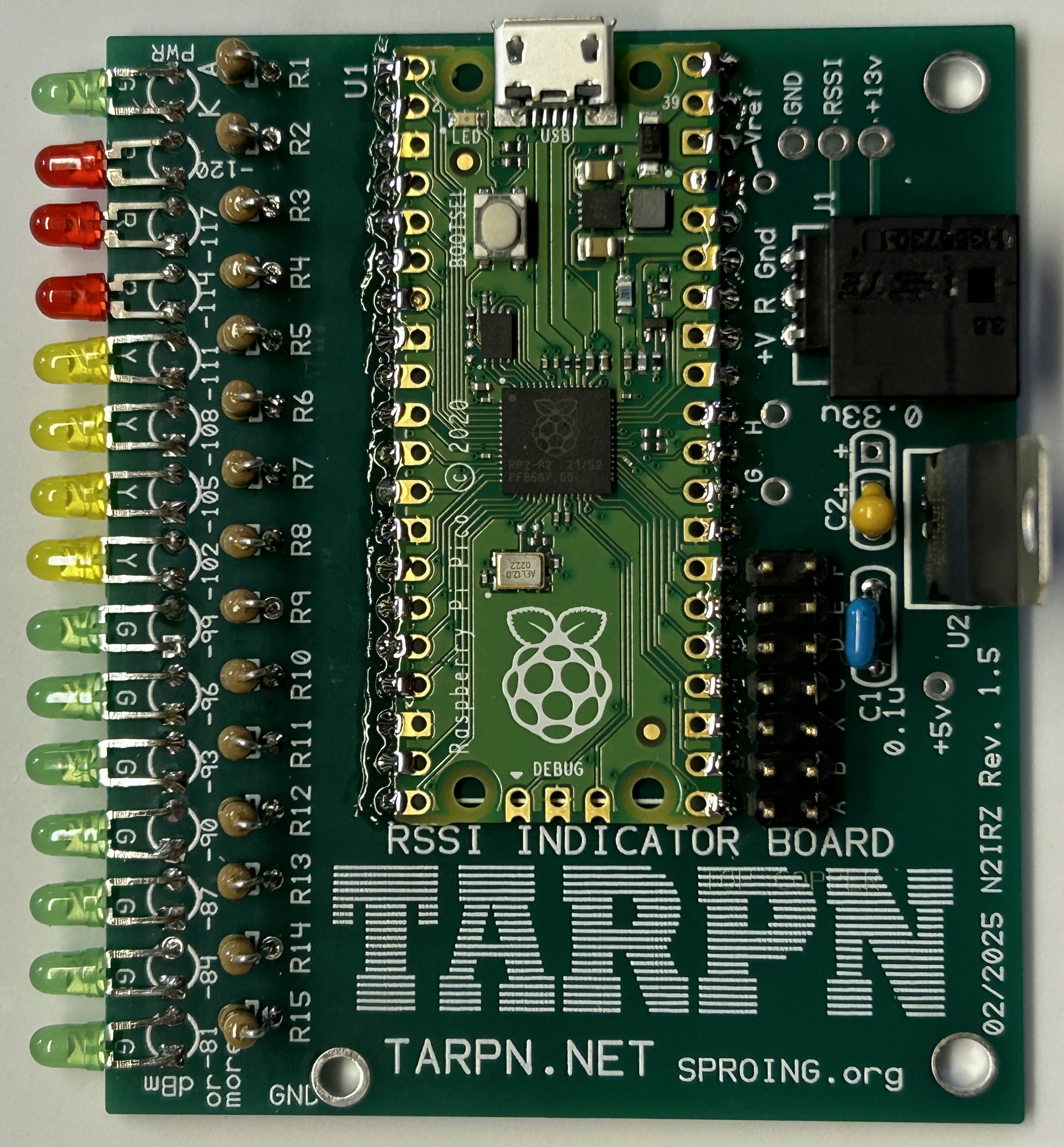
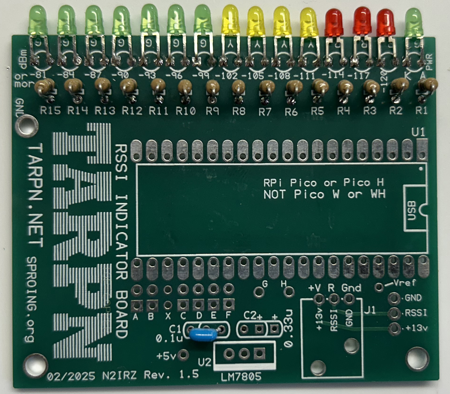
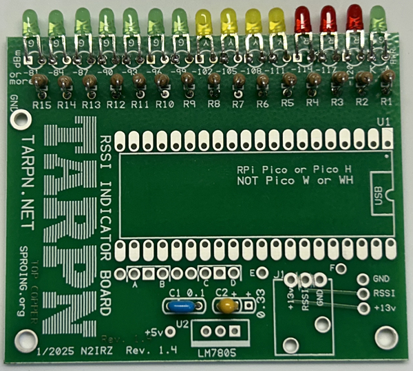
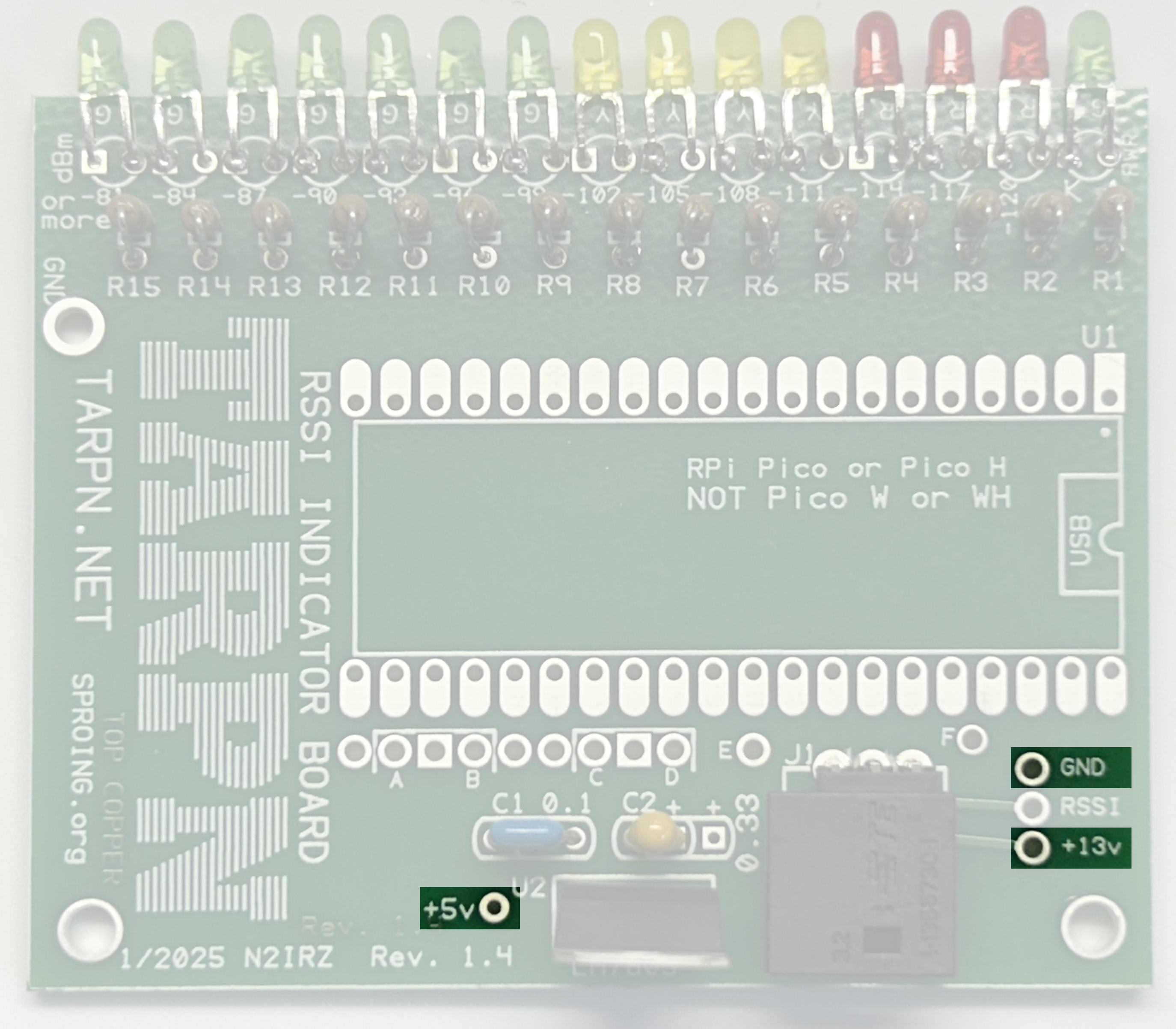
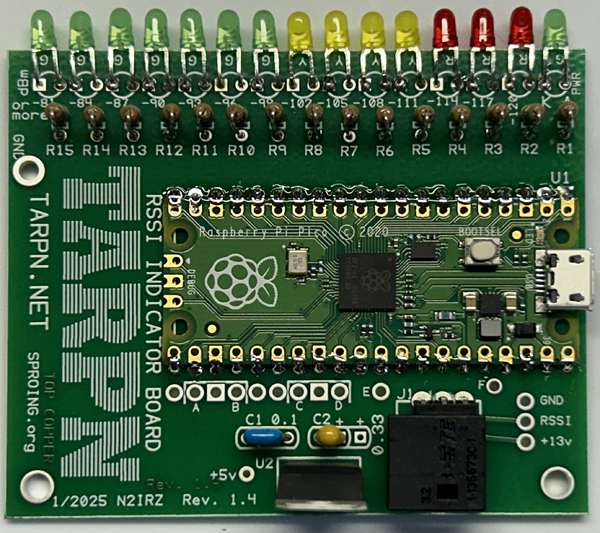
The N2IRZ RSSI Board displays the strength of a radio's received signal, much like an S-Meter in most amateur radios. Because TARPN Networks tend to use surplus commercial radios, which typically do not have S-Meters, we use this board as an aid to link diagnosis and performance. Having a Received Signal Strength Indicator (RSSI) helps us in a few ways, including:
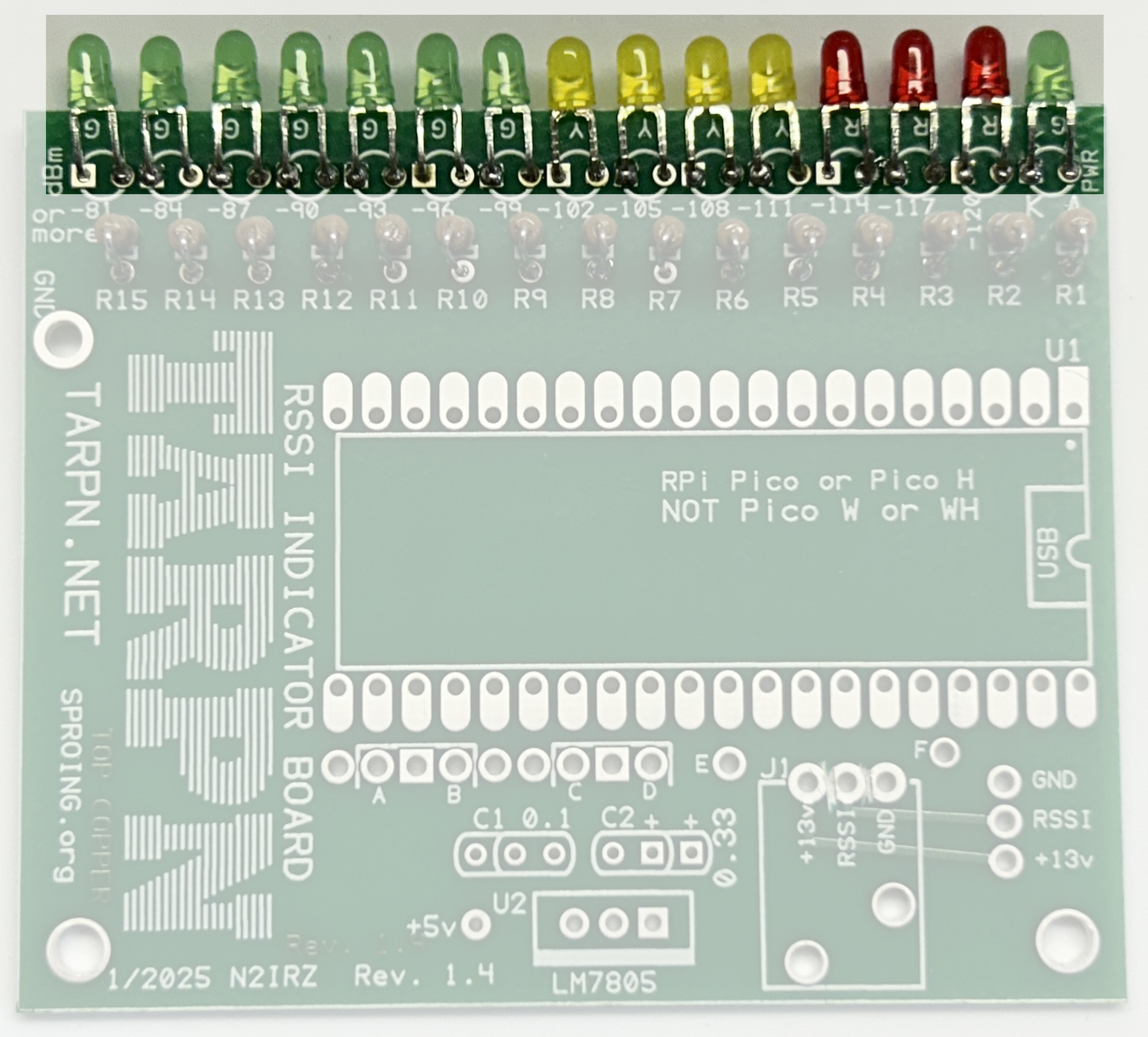
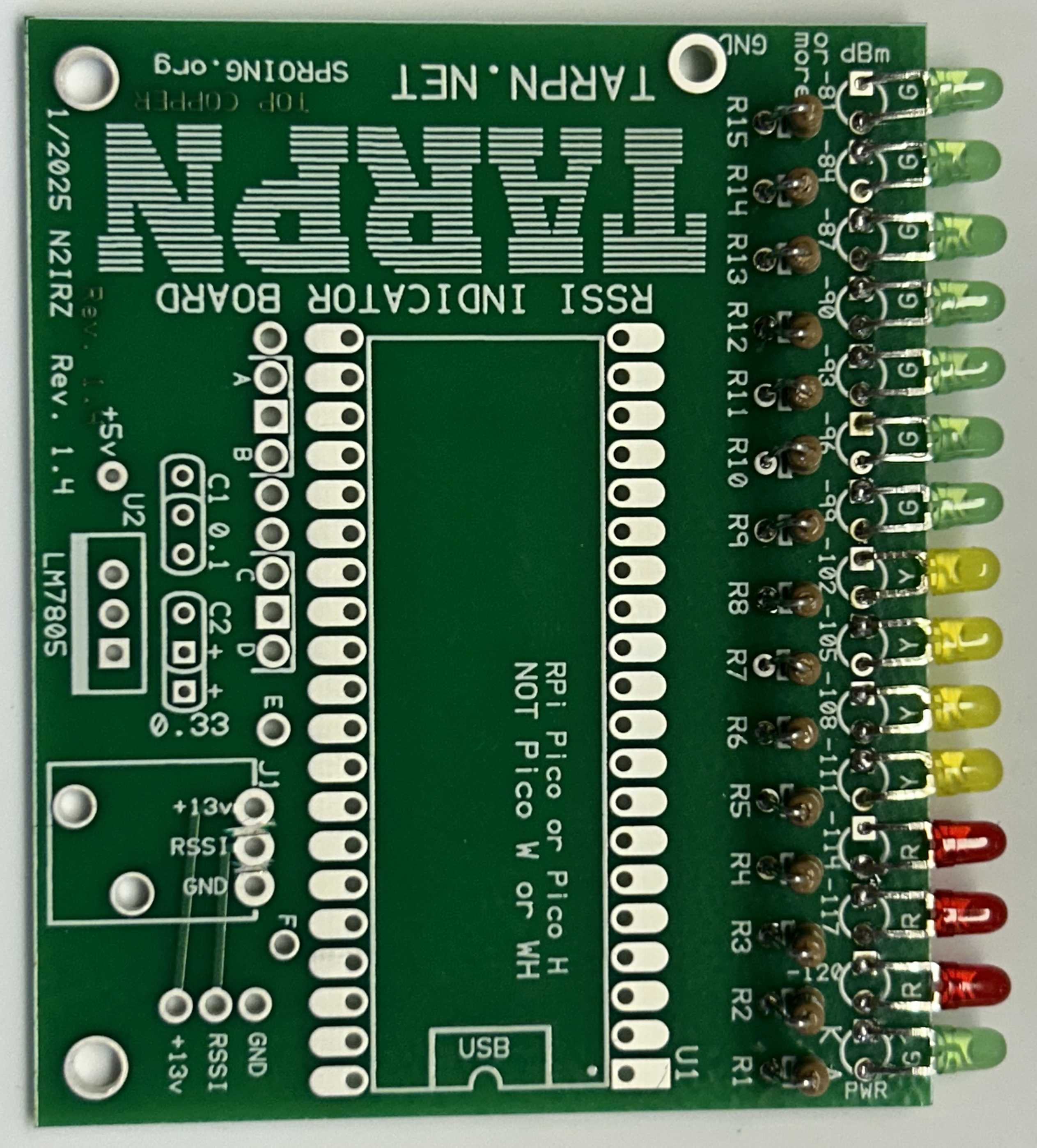
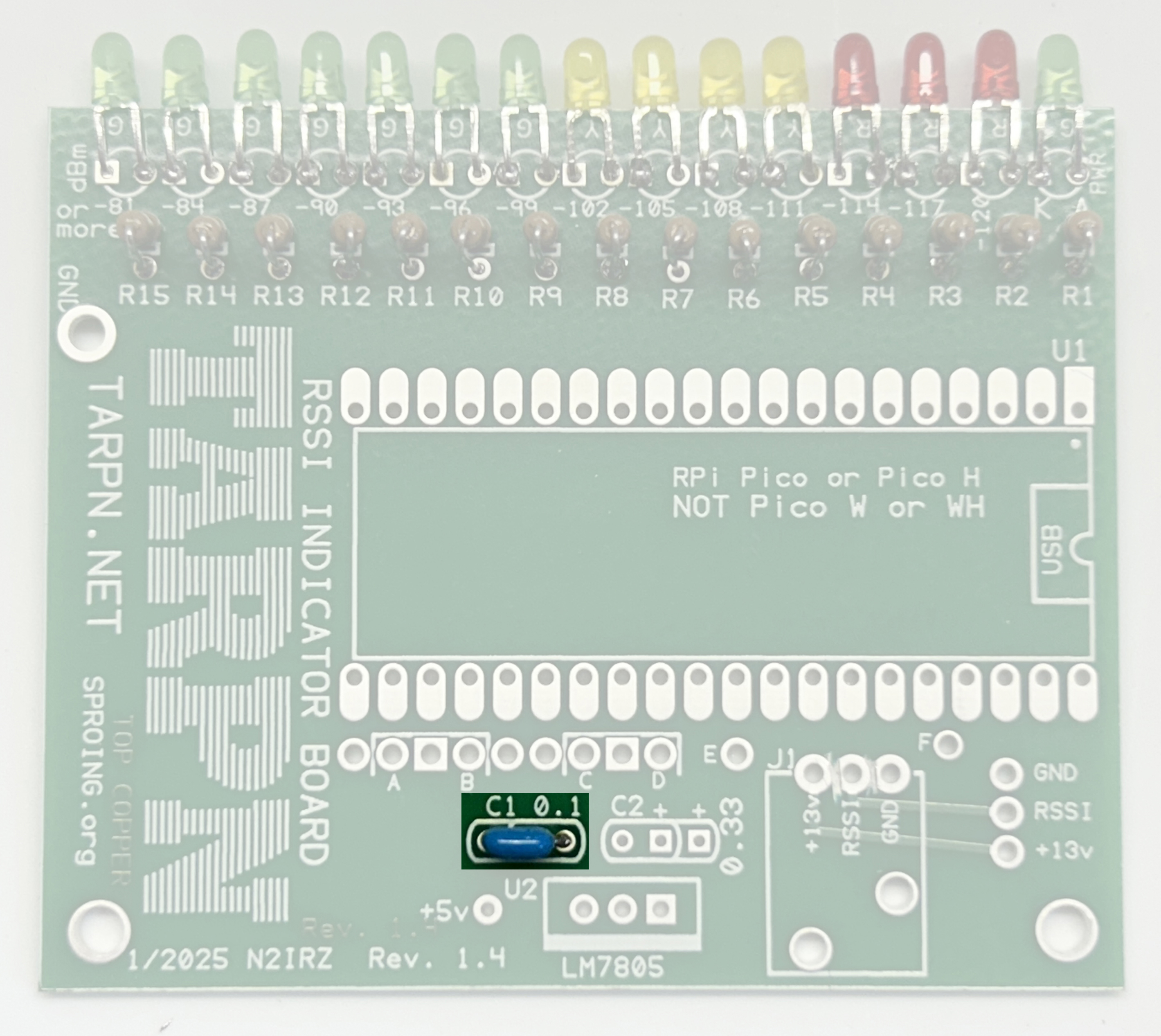
The core computing power comes from a Raspberry Pi Pico (1st generation, RP2040). software on the Pico reads in the radio's RSSI voltage and displays a relative value by lighting successive LEDs on the board. These LEDs are driven by raising the voltage on specific GPIO (General Purpose Input/Output) pins on the Pico. Resistors limit the current to the LEDs, protecting both the lEDs and the Pico. An on-board power supply accepts power from the radio (typically 12-volts, allowable is 8- to 18-volts) and converts it to a clean 5-volts for the Pico. A robust automitive-grade signal input connector allows for easy interfacing with the radio. Specially-selected LEDs, rated at a 2 mA current draw, are used to avoid overloading the Pico.
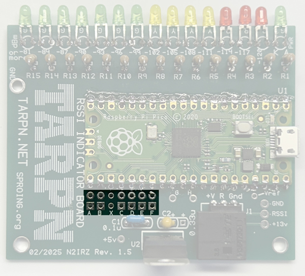
A signal selector area allows the N2IRZ RSSI Board to be used with radios having different RSSI vs Antenna Input Level curves. At this time, the TAIT 8000-series radios and Kenwood TK-x90 series radios are supported; this page will be updated when a radio is added. The user must place the included jumper on the correct header location for the RSSI board to function: A missing header displays an error condition (LED1 & 2 blink alternately)
The software is written in Python, and is downloadable and open-source. If you desire to add or change the software, it would be a kindness to send a copy to N2IRZ at his QRZ.com email address.
The software uses an onboard Analog-to-Digital (A/D) converter to measure the analog RSSI voltage. It then lights a number of LEDs sequentially to visually indicate the signal level. As an aid to recognizing very fast signals, the highest signal level received in the last few moments is indicated with a brief hold time.
The end-user can load new software, provided by N2IRZ, others, or self-developed. The peak-hold time, the voltage calibration - indeed, any aspect of the board's operation - can be customized by anyone who is moderately fluent in the Python programming language.
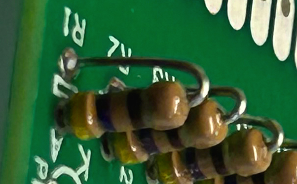
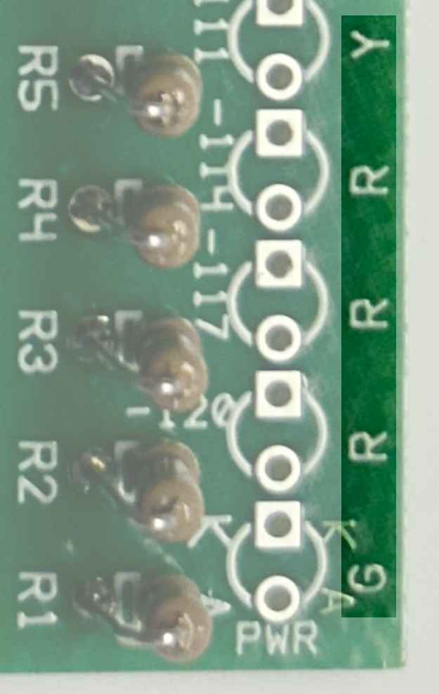
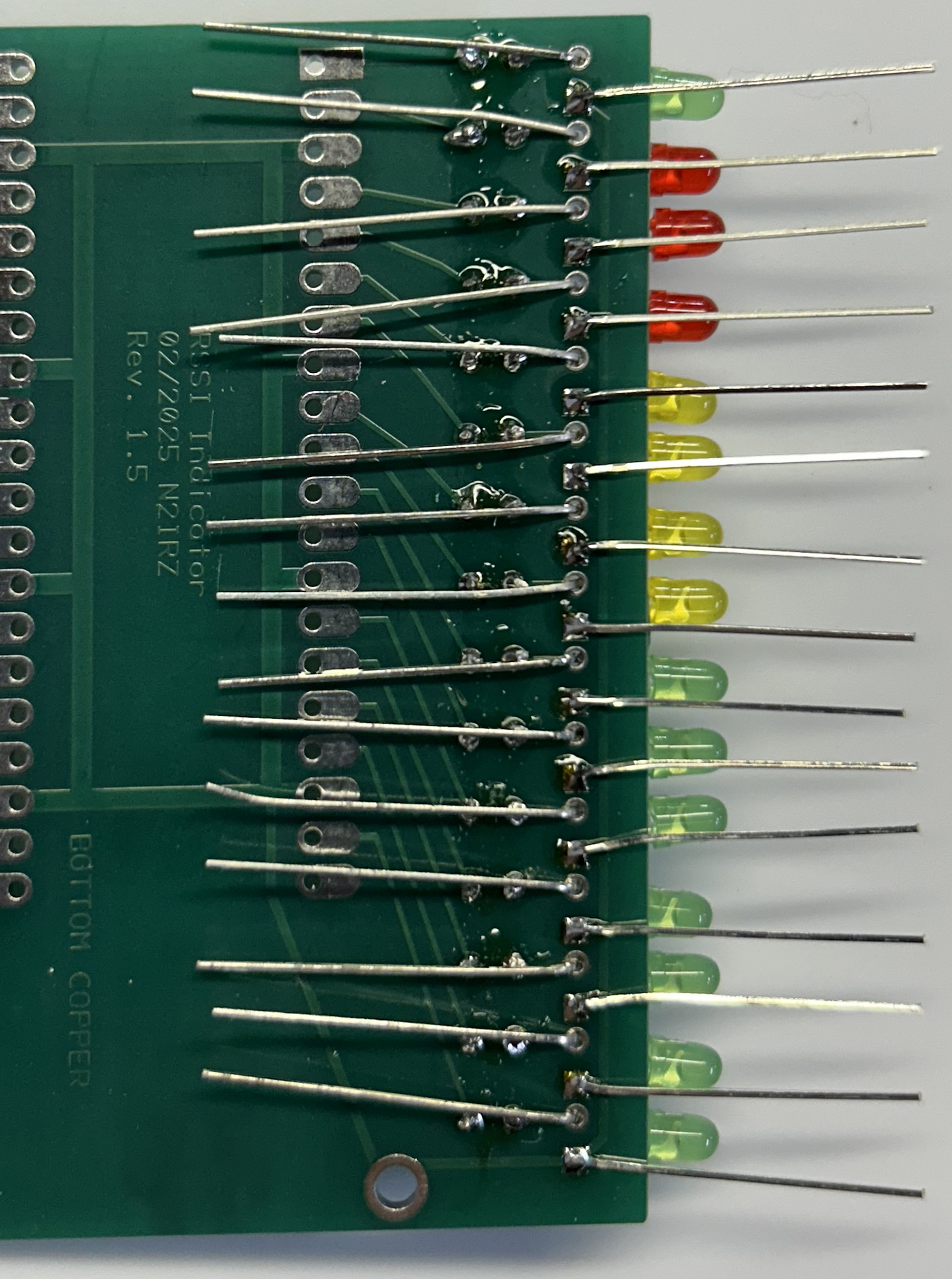
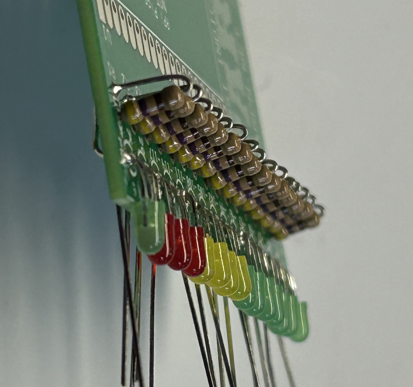
| 1.1 | Install R1 thru R15 | For this step, you'll need the 15 resistors included with the kit. One at a time, bend each resistor's wire lead as shown, then insert it into the board with the body of the resistor nearest the edge of the PC Board, as shown. Once the body-side lead of all 15 resistors has been soldered, carefully adjust the resistors so they all stand up straight and even. While alignment is partly for looks (you want the board to look nice) it also helps avoid short circuits and other future problems. |
    |
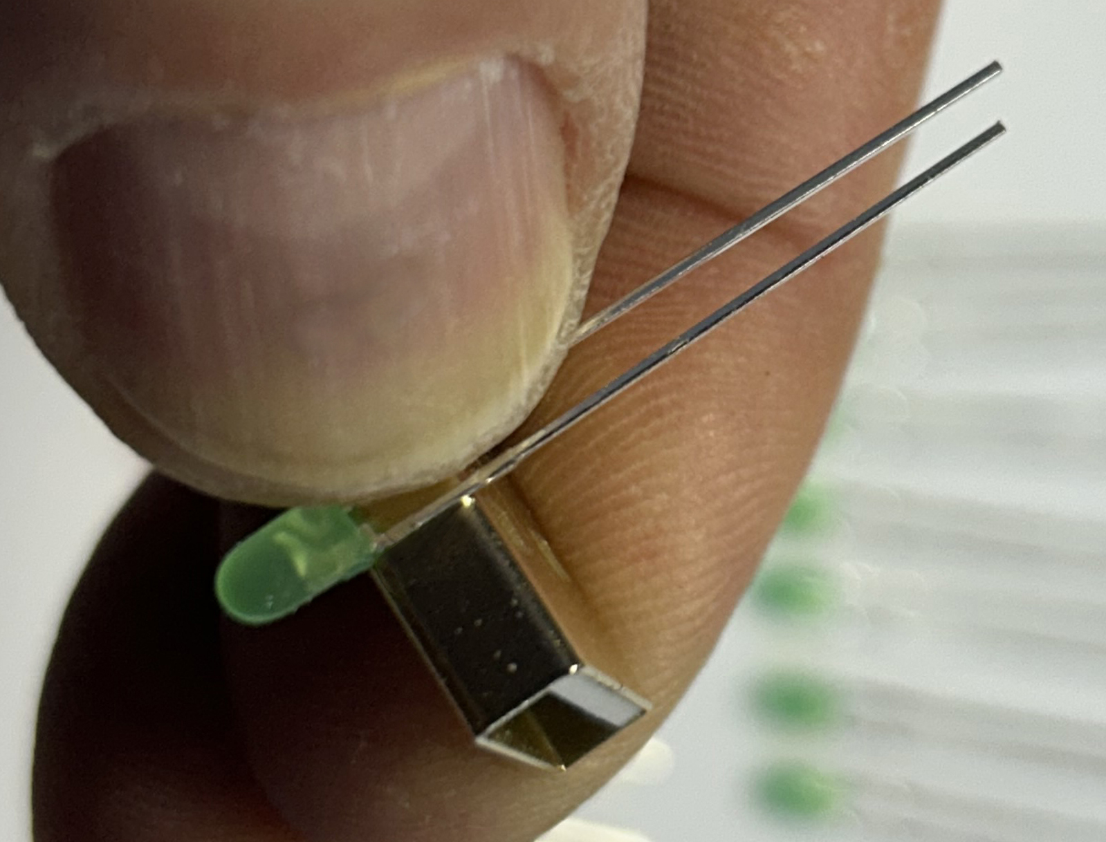
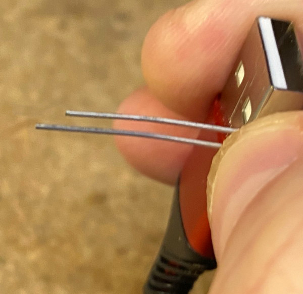
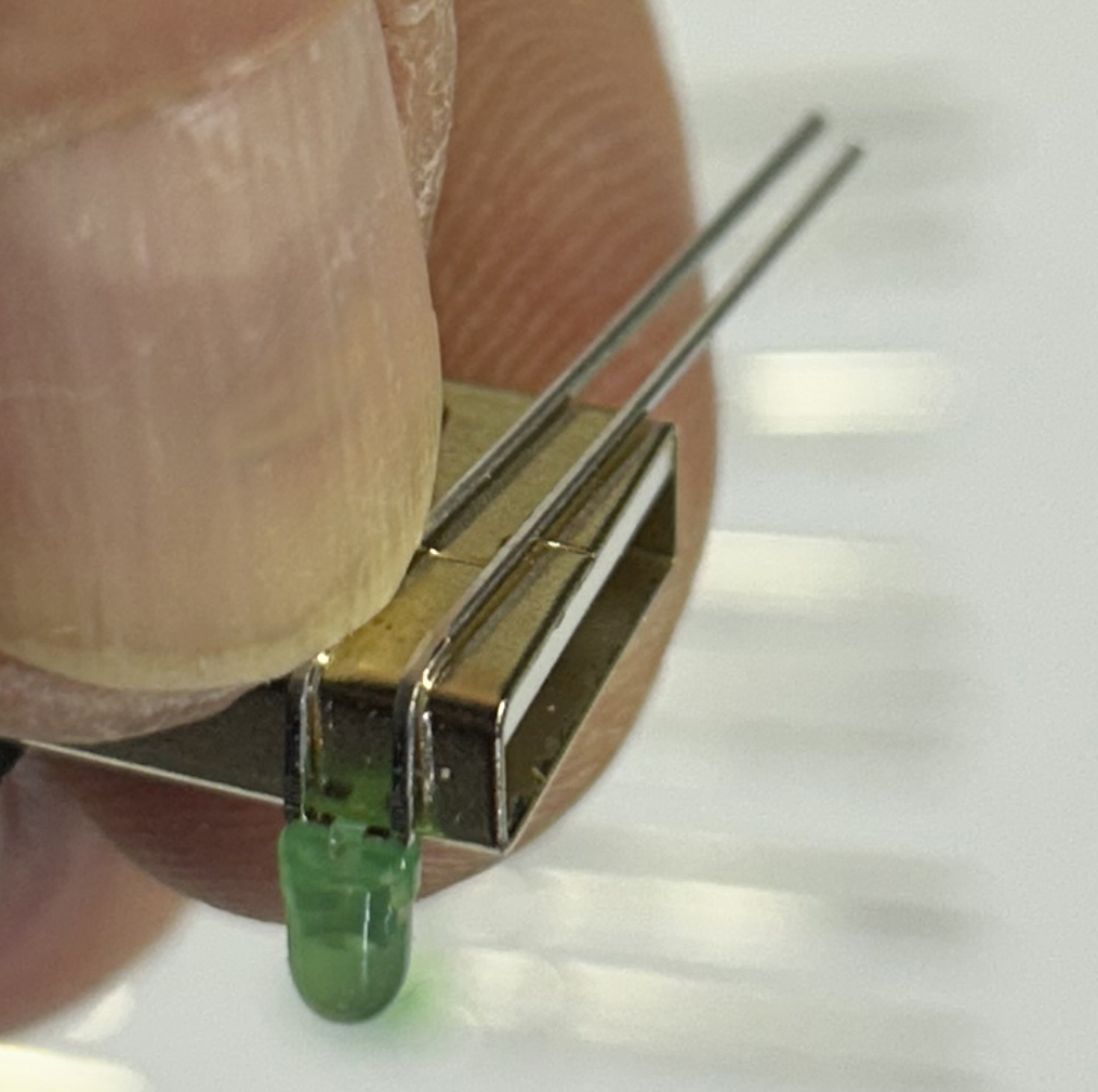
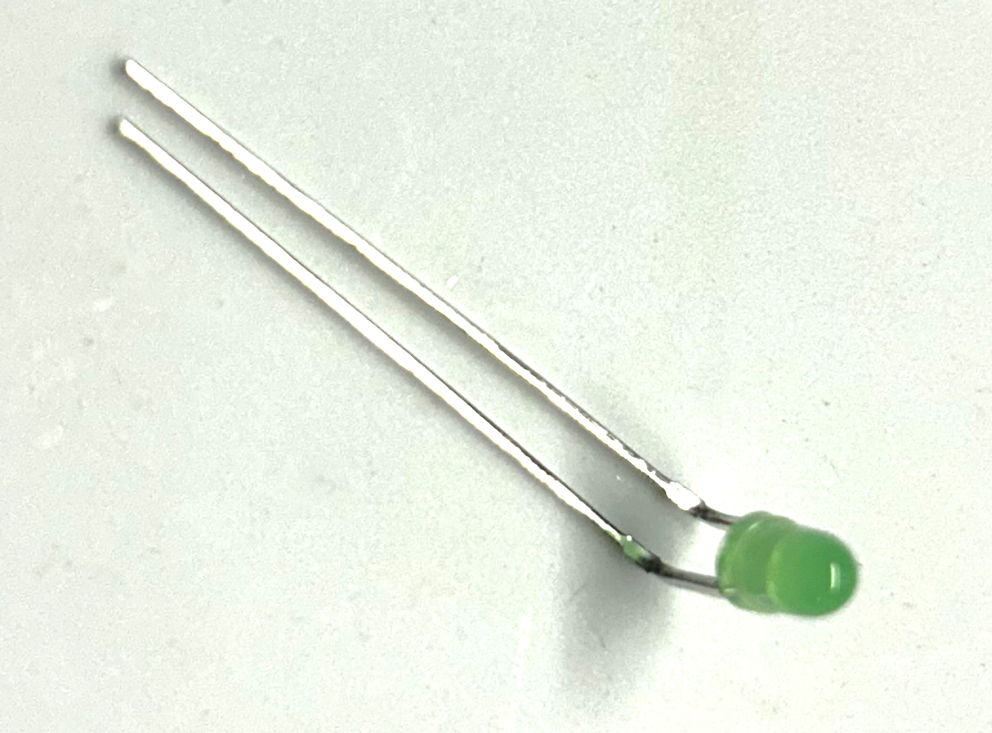
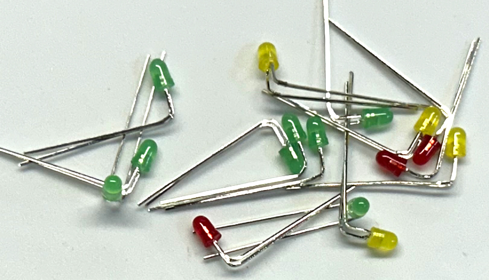
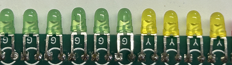
| 1.2a | Prepare the LEDs | For this step, you will need the fifteen LEDs and a USB-A connector (as a bending guide).
For all fifteen LEDs:
|
|
| 1.2b | Install the LEDs |
|
|
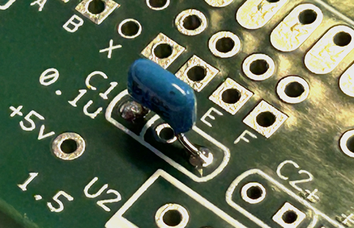
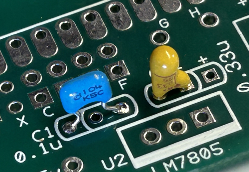
| 1.3 | Install C1 
|
For this step, you will need the 0.1 uF monolithic capacitor. Note: The PC Board can accommodate parts with a wire lead spacing or 0.1" or 0.2". Be sure to use the correct two holes for a 0.1" spacing part. The 0.2" spacing part uses the two outer holes. Install C2 and solder it. Polarity is not important for this part. Clip the exceess wire leads. |
|
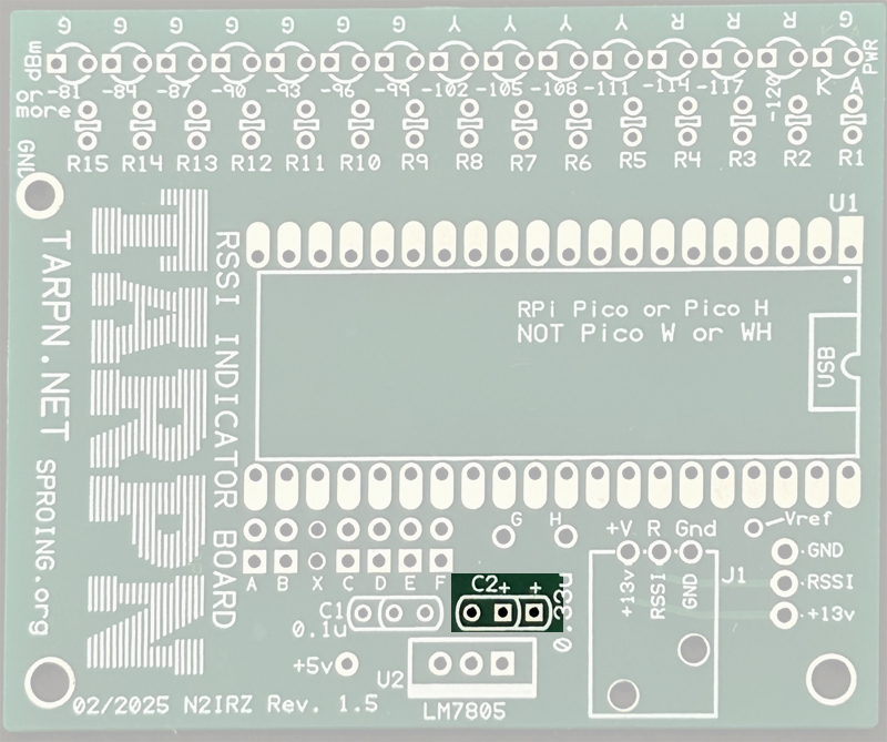
| 1.4 | Install C2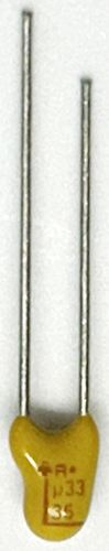
|
For this step, you will need the 0.33 uF tantalum electrolytic capacitor. Here, the polarity is important: On the capacitor body, there is a marking for +, so be sure this wire lead (which is longer) goes into one of the two holes marked + on the PC board, and the shorter lead goes into the unmarked hole (closest to the "C2" text). Note that the PC Board can accommodate parts with wire lead spacing of 0.1” or 0.2”. Be sure to use the correct two holes for a 0.1” spacing part, while the 0.2” part uses the two outer holes. Solder and clip the leads. |
|
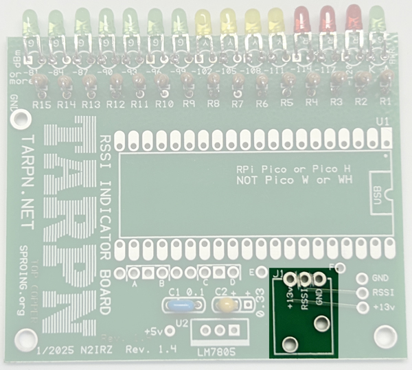
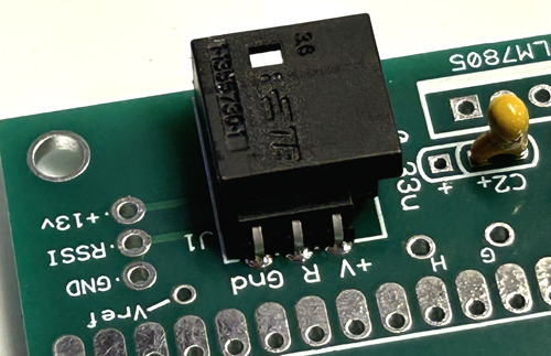
| 1.5 | Install J1

|
For this step, you will need the J1 male connector body. Install J1 by snapping it into place on the board, then soldering the three pins. |
|
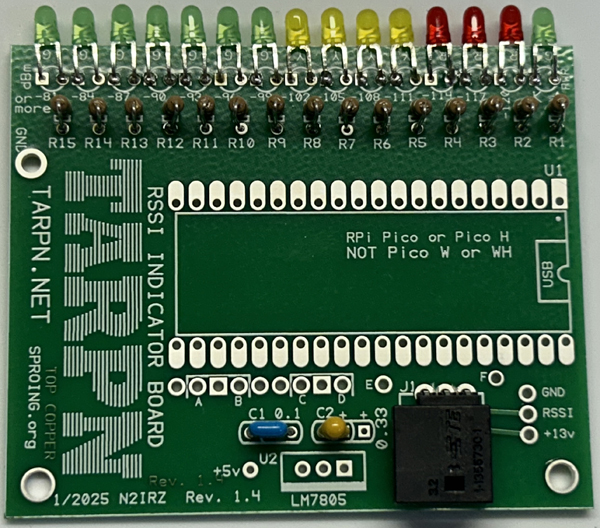
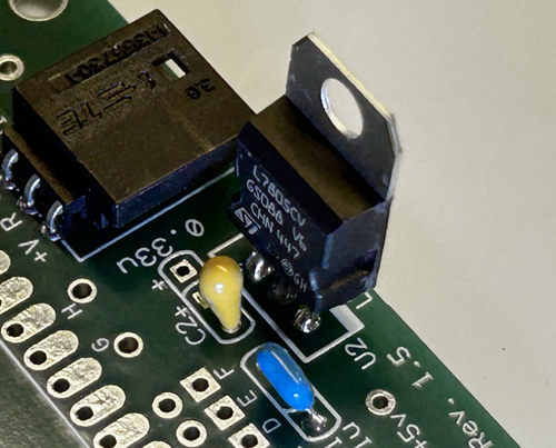
| 1.6 | install U2
|
For this step, you will need the LM7805 voltage regulator. Install the U2 voltage regulator, for which polarity is important: Make sure the metal tab on the voltage regulator is facing the edge of the PC board. Solder one lead, bend the part so it is exactly upright, then solder the other two leads. Clip off the excess. |
|
OK, now take a short break
| 1.7 | Install U1 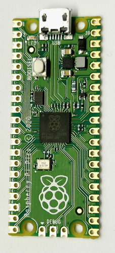
|
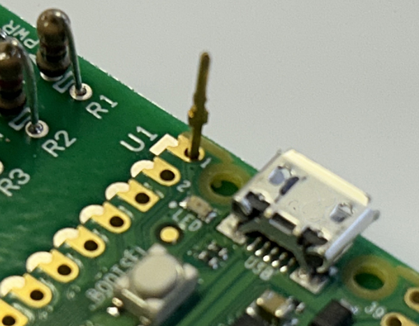
For this step, you will need the Raspberry Pi Pico. Install U1, the Raspberry Pi Pico. Note the orientation, with the USB connector at the edge of the PC board. Installing this incorrectly can permanently damage the Pico, and once installed it is nearly impossible to uninstall. Use some wire (or similar) to align the holes in two corners of U1 with the holes in the PC board. With the board aligned properly, solder two of the Pi's edge contacts to the PC board, then remove your alignment wires. |
|
| 1.8 | Install the Header
|
For this step, you will need the 2x7 0,.100" header. Install it and, while holding it into the board with a finger, solder any one pin that is not touching your finger (it gets hot!). Verify that the header is tight against the board, resoldering that one pin if needed. Then solder the remaining pins. This completes the board assembly. Please continue to the next step to load the software onto the board. |
  The image below shows a Berg Jumper installed; it is yellow for better visibility in the photo, the one included in the kit is black. 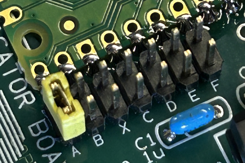
|
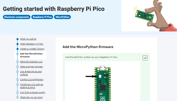
| 2.1 | Install Thonny | If you don't have the Thonny software application (Supports Windows, Mac and Linux), then please Download It HERE, then install it. |
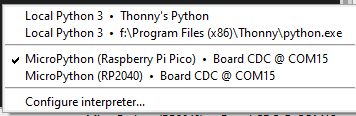
| 2.2 | Install Micropython |
|
 |
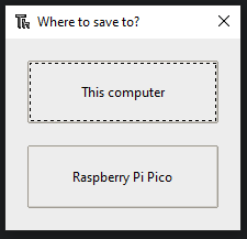
| 2.3 | Dowload and Install the RSSI Software |
|
|
We can now test the software to see that it is responsive
Follow these steps to assemble the RSSI cable to your existing Radio-to-TNC Cable. Note that the specifics differ according to the radio type.
If you have not yet built a radio-to-TNC cable for your setup, visit the TARPN page appropriate for your radio for information on building one.
| A | TAIT 8000-series Radios |
|

 Images coming soon! |
| B | Kenwood TK-790 Radios | NOTE: This should also work for the TK-690, but it has not been tested.
Note that Pin 13 (TXA), Pin 7 (GND), Pin 15 (PTT) and Pin 16 (RXA) should already be connected (to the TNC). |
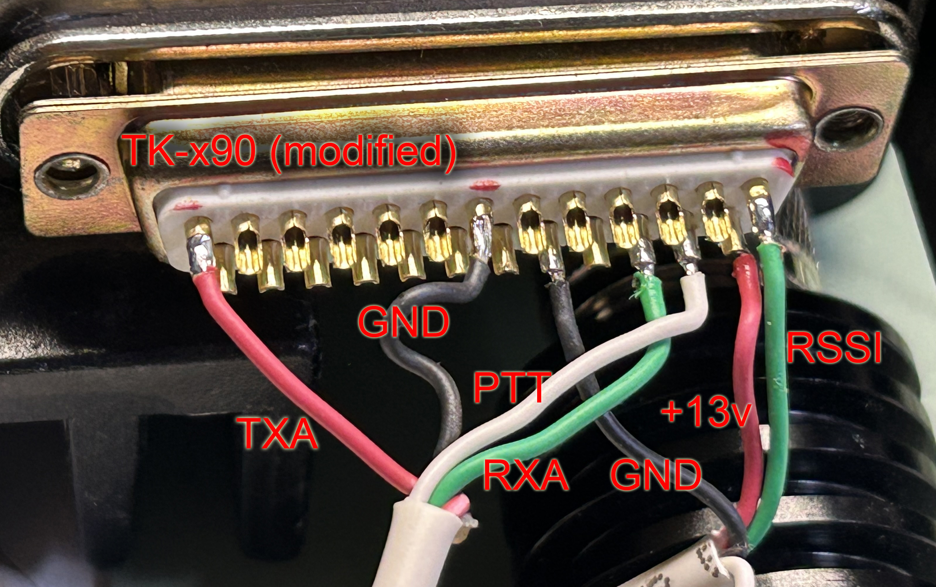 This image shows a fully-populated DB-25M connector with the pin signals labeled. |
Some information about preparing your radio to deliver the signals the RSSI Board needs:
This website is maintained by Don Rotolo, N2IRZ. Contact me via the information on QRZ.COM
Updated 10MAR2025